Adventures in Steelwork continued…
(or Chris Discovers Plasma)
The last post dealt with the mast steps, bulkhead tabs and aft peak framework. The order of work was very much dictated by the presence just ahead of me in the shed of the beautifully varnished hull of Rumbuster, a one-off, 36ft Sparkman and Stephens design, which I have known for most of my life, as she was once owned by Admiral Charles Williams and was berthed at Hornet Sailing Club in Gosport, from where much of my childhood sailing was based. She was so close to my bow that I really didn’t want to do any of the steelwork on the foredeck until she had left the shed to be relaunched. Fortunately this happened a few weeks ago, so I was able to crack on with what I wanted to do before time ran out.
For the last few days as she was being prepared for launch, I had a few other bits I needed to tackle. First of all, I had been persuaded that the best way of cutting the holes in the hull I needed for through-hull inlets and outlets to be fitted was not to use a heavy magnetic drill (which might not stick properly to a painted and slightly bent, sheet steel surface, and for which each cutter costs a small fortune), but to invest in a small plasma cutter. This I ordered, and when it arrived I found I needed a 16 Amp power supply and an air hose, so these were arranged, the former by speaking nicely to Dave and Alistair at the boatyard; the latter by ordering it from Screwfix, whence it arrived, eventually. Whilst waiting for these pieces of the puzzle to drop into place, I went about fabricating some mooring posts for the foredeck.
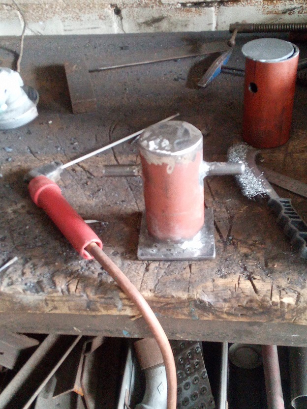
Now, when I bought the hull, it came with several crates of fittings of various quality and utility, and amongst these were a number of alloy mooring cleats, and I was quite happy to use these to move the boat last year, especially as holes were already drilled for a pair of cleats on the foredeck. However, one of the benefits of a steel boat is that fittings can be fabricated fairly cheaply out of steel and welded to the hull, which eliminates the risk of electrolytic corrosion. When I thought about the implications of having alloy mooring cleats attached to a steel hull with stainless steel bolts, I thought that this had potential (literally) to create a nice battery, and would be a source of corrosion which could easily be eliminated. Besides, the Wylo is a roughty-toughty (pron, “ruffty-tuffty”) kind of a boat, and deserves some seriously solid mooring equipment, especially with the kind of use I would wish to put the boat to. So I made up three mooring posts out of good, solid steel pipe and rod, with plate base and top. This was another fun exercise in improving my welding skills and I ended up using a very fancy, water-cooled machine which Dave has in his fabrication shop. First, I needed to cut the pipe into three 150mm lengths, which I could have done with a grinder, but I had spotted lurking in the shop a rather fine-looking machine, which I have since named the Tyrannosaw, but at the time I approached Dave to ask if I could use it, simply called the “angry mega-hacksaw thing”. Actually it is a very good machine and easy to use, and looks fun when in action:
After I had welded the posts together and ground the messier welds smooth, I had to decide upon their positioning. I had already decided that I needed three posts due to the positioning of the foremast, as to moor the vessel alongside, it would be tricky to work from a single post forward on the centreline, as the mast is in the way, so I positioned one each side where the holes had already been drilled for the cleats. The posts would be positioned so that the load on them could be transferred into a fore-and-aft deck beam beneath them, gaining further strength from the reinforcing pads already in place for the cleats, and conveniently covering the pre-drilled holes. These, however, would not be in an ideal position for a mooring line from a buoy, as the lead from the bow roller would be obstructed by the foremast, so I also chose to position one right forward, ahead of the mast and adjacent to the bow roller. The roller assembly needed a bit of modification, as the middle aperture was originally designed for a bowsprit, so had cheek plates which extended quite far aft. These were cut back with the plasma machine to be in line with the join of the bulwarks to the outboard cheek plates, and then there will be a roller in the middle aperture for mooring lines, with a further roller either side for anchors.
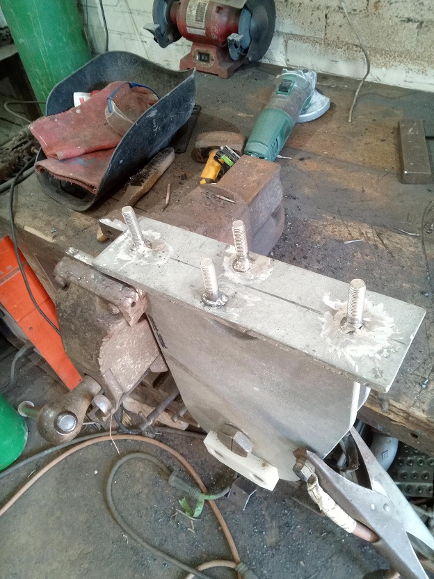
Another complex job which required a lot of measuring, head-scratching and finger-crossing, was getting the positions right for the four studs which will allow for the centreboard holder assembly to be attached to the underside of the centreboard case flange plate. Once I had worked out the positions on the holder (the holes for the studs were already drilled in the flange plate), I made a template, cut the heads off four bolts, held my breath and welded them onto the piece. With some luck, they ended up in the right positions, and having drilled the holes out ever so slightly to allow some wiggle room when it is all assembled, dry fitted them together successfully.

However, doing this and other cutting on the foredeck and any welding was still waiting for Rumbuster to move, and by now I had all the bits I needed for the plasma cutter, so I set about learning how to use this fantastic machine. To explain how it works, I will leave it to one of any number of websites you can find by searching for “how does a plasma cutter work”, because to me it is just another kind of magic.
“Plasma cutters work by sending an electric arc through a gas that is passing through a constricted opening. The gas can be shop air, nitrogen, argon, oxygen. etc. This elevates the temperature of the gas to the point that it enters a 4th state of matter. We all are familiar with the first three: i.e., solid, liquid, and gas. Scientists call this additional state plasma. As the metal being cut is part of the circuit, the electrical conductivity of the plasma causes the arc to transfer to the work.
The restricted opening (nozzle) the gas passes through causes it to squeeze by at a high speed, like air passing through a venturi in a carburetor. This high speed gas cuts through the molten metal. The gas is also directed around the perimeter of the cutting area to shield the cut.” (https://torchmate.com/white-papers/How-a-plasma-cutter-works)
Having found some scrap to practice on, my first efforts were rather abortive. I seemed to be able to strike an arc briefly, but then this would stutter out after a second and then I’d have to let the air purge through before trying again. Eventually after a bit of consultation I discovered that this was no fault of the machine, but merely bad technique on my part, and I had to strike the arc and get cutting by holding the nozzle a millimetre or so off the surface of the material and drawing it across at a steady speed. Once I had this I was able to practice cutting first straight lines, then freehand curves and circles (for which I used pre-cut wooden guides of various sizes). It all seemed quite straightforward, so I prepared to cut my first holes in the hull.
Quite naturally, once you were on a vertical surface and working just above head height, it turned out not to be as easy as on a workbench with scrap metal. The guides helped me stay with a vaguely circular shape, but it was far more difficult to keep a steady hand and the nozzle just off the surface of the material, so my first holes, for the bilge pump outlets, were somewhat messy. With a bit of elbow grease with a grinding point in a drill, and a half-round file, however, these were cleaned up to a fairly regular shape with clean edges so as to be paintable.
I next moved into the cockpit, and cut an aperture for the engine control lever in the port side of the well. For the move last year I had temporarily rigged the lever through a piece of plywood bolted into the aperture which was already cut for the quarterberth porthole, but as I would now be using this for its intended purpose, a new location for the lever was required.
Next I moved down below and forward to cut a hole for the heads inlet and also for the log impeller. The former was a bit of a cock-up, as I managed to have a brainfart and used the wrong sized guide, so I ended up with a hole for a 1 1/2″ BSP hull fitting rather than the 3/4″ one I had intended. I could of course weld a disc of 5mm steel back into this hole with the correct hole pre-cut in it, and I may well do this, or use a larger hull fitting. The other cutting job I had to do was to crop out the existing standpipe which I can only presume was intended for a heads inlet, but which, with my planned layout, would project right up through the middle of the sole between the workbench and the heads, and cause a bit of an obstruction. I had already decided, as this pipe was set vertically, that if I cropped this right back close to the shell plating but with the top horizontal, I could use it for the echo sounder transducer so that it points vertically downwards, rather than perpendicular to the hull plating. The pipe’s bore is about 2″, so this will be filled with thickened resin, which can then be drilled out at the correct bore and angle for the transducer, and a fairing piece fitted on the outside.
There was a final bit of steelwork I wanted to complete down below before starting on the foredeck, and this was actually on the underside of the foredeck. When I got the MacSweeneys to do the work on the foredeck last summer, moving the foremast partner ring, building the beds for my windlass and capping off the bulwarks with stainless bar, they left a rather untidy pair of cut-off beam ends either side of the partners. I had originally specified a new transverse deck half-beam either side of the partner ring, but they demurred, and assured me that what was there would be amply strong enough, and maybe they were right. However, it left two diagonal half-beams with abrupt, perpendicular cut-off ends, which looked awful and unfinished. So I gritted my teeth for some overhead welding, cropped the ends of the vestigial half-beams back a bit and welded in two new transverse beams to tidy the arrangement up and, I think, provide some reinforcement to the deck where it is needed.
Before: me wedged right forward, where you can see the untidy cut-off end of the old diagonal half-beam 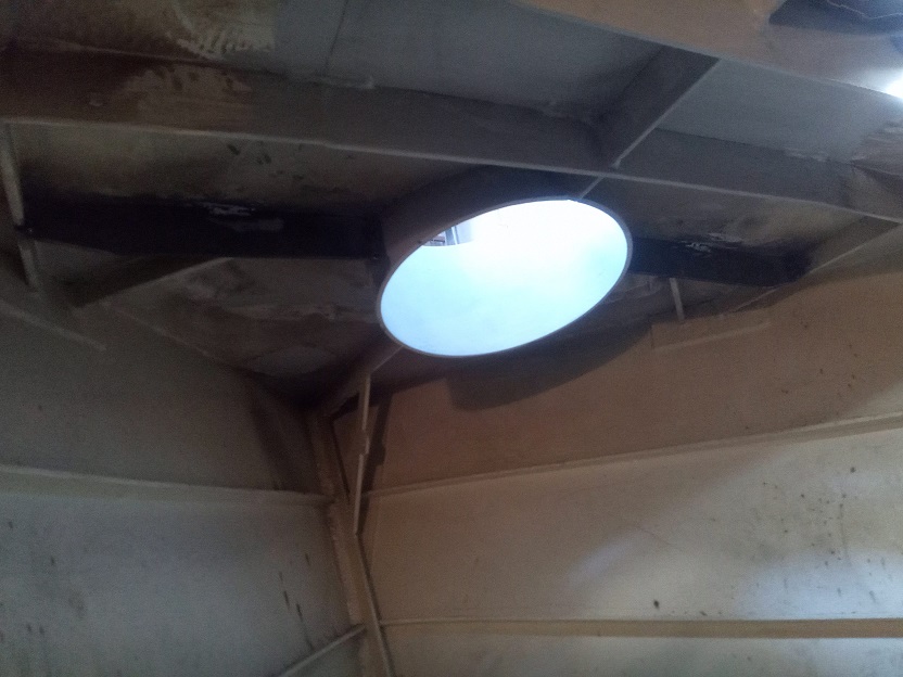
After: new transverse half-beams in place, with the diagonals cropped back and forming part of a fairly substantial web of support to the partners
Finally I could get onto the foredeck, with Rumbuster now outside and being rigged for her relaunch, so I moved all the equipment forward, cleared away the fan and its trunking, and got started. The first job was cutting new apertures for mooring fairleads. There were some existing cut-outs right in the eyes of the ship, again really too far forward, given the position of the foremast, and the mooring posts. So, using my wooden guides again, I cut apertures further aft, in a location where the bulwark was already strengthened for some bolt-on alloy fairleads (see above comments on corrosion). I had already procured some nice stainless fairlead liners, which I then welded into place in the new apertures. Again, I had to devise some new techniques to ensure these were welded in all-round, inside and out, and then had an awful lot of grinding to make them look seamless with the plating. The existing apertures were then blanked off with some pre-cut bits of 3mm plate, and these produced some very satisfactory welds and looked great once ground smooth. Looking at the pictures, you will notice that there are holes drilled at intervals along the rail. These were presumably intended for through-bolting a nice wooden capping rail (under which the steel would then have rusted merrily), which I of course have now replaced with stainless rod. The holes will therefore need plugging, but as they are nicely coated with an epoxy paint system, the advice has been to use an epoxy filler for this job rather than weld. Having done a handful of holes with weld, I fully concur, as welding them up will be very time-consuming and potentially do more harm than good.
After these jobs, I got on to welding the mooring posts in position. I started with the forward one, and found that the deck in this area was quite indented. Having chosen a position where it would benefit from the strength of the centreline deck beam, as well as providing a surface which best matched the slightly convex (due to heat in the fabrication process) underside of the post, I first tacked it in place, and then ran numerous beads of weld around the four edges, in order to give a neat fillet and compensate for the uneven surface, but also to provide ample strength for the fitting. The deck around the other two was not so misshapen and the process was more straightforward, both being welded on in reasonably short order.
The very final job on the foredeck for this leave was to cut the hole and weld in a spurling pipe with a threaded top for a screw-on cap. This will be for the second anchor, which will stow on the foredeck for quick deployment, and the cable will be hooked to the inside of the screw cap (on a swivel) so it can be quickly shackled to the anchor. The pipe itself was cut down from the standpipe I had previously cut out in the forecabin for the echo sounder.

A clear view of the old, blanked-off fairlead, with the new one in the background 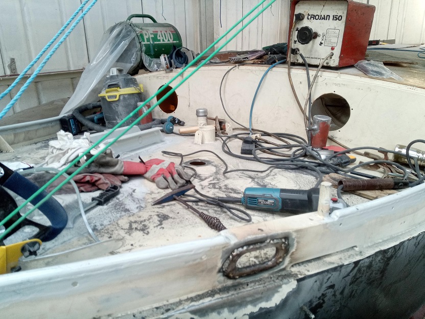
I like to keep a tidy workplace… 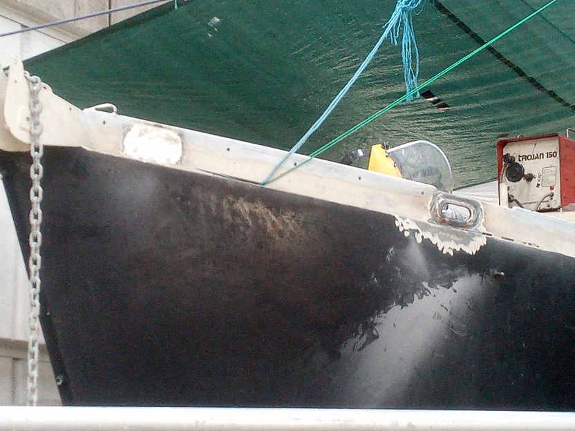
Port bow 
Starboard bow 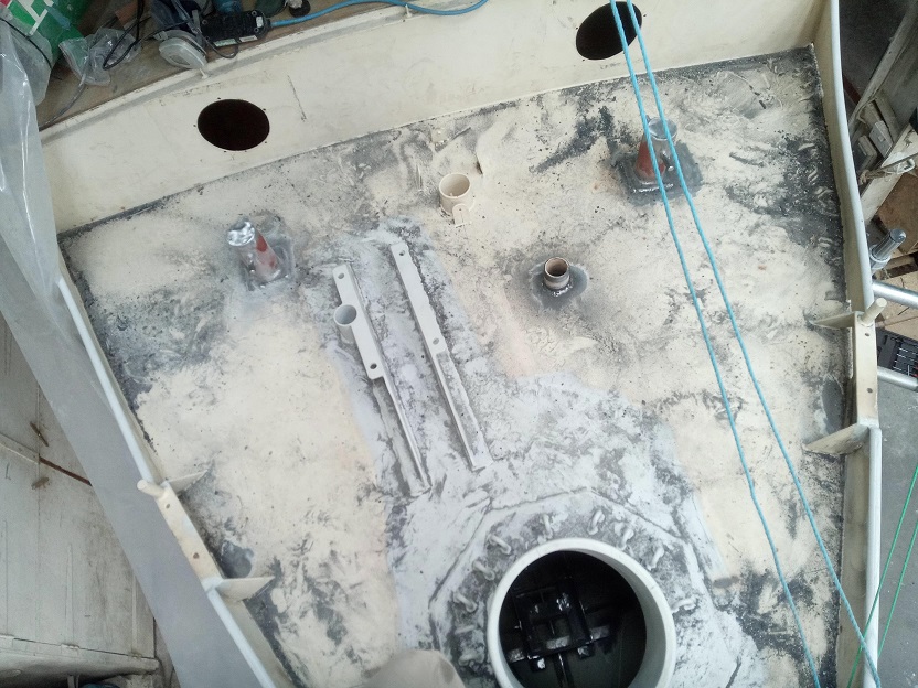
Finished job, from above, before hoovering! 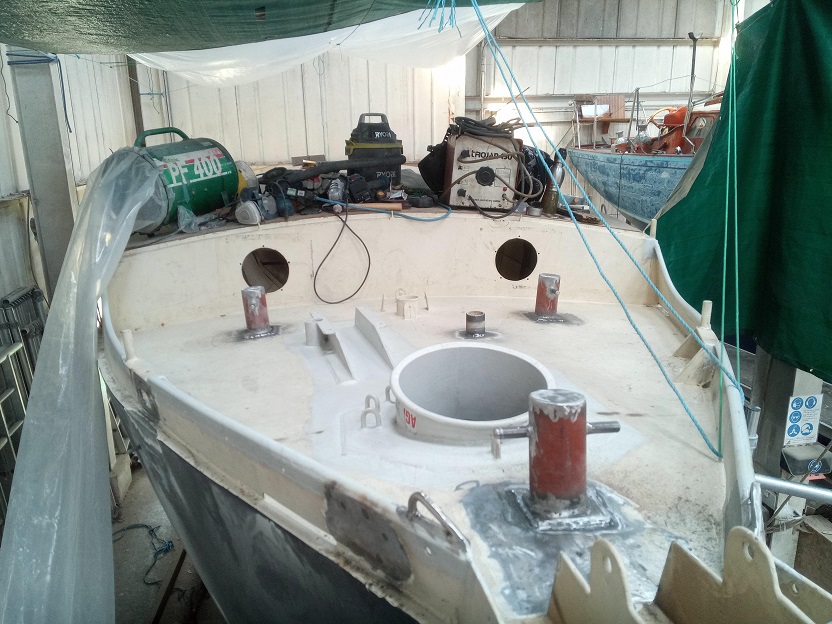
Finished job from right fwd – note the bow roller arrangement and new eyes for guardrails on the rail
Having written two posts now, I realise that I have achieved a great deal in the month-and-a-half I have been at it, and feel very satisfied. I hope in my next leave period to get all the steelwork finished and all bare metal painted and a top coat done down below. I would have spent another month or so on doing this right now, but the nature of my current employment on Pelican is that I am only paid when on board, so with three months off I have had to arrange for some work in my role as a Royal Naval Reservist for several weeks to top up the coffers. At present therefore I am based in Dorset as a military liaison officer with the Dorset Local Resilience Forum, which is quite interesting work ,and allowing for the aches and pains brought on by the last couple of months to subside!