
Summer again – it must be mast work!
Most of my work on the boat has been interior fitting out for the last several months, so with some warm weather (not dry though) on my return from my last (literally my last) trip on LOTG, it was time for some critical work on the mainmast and some finishing work on both masts.
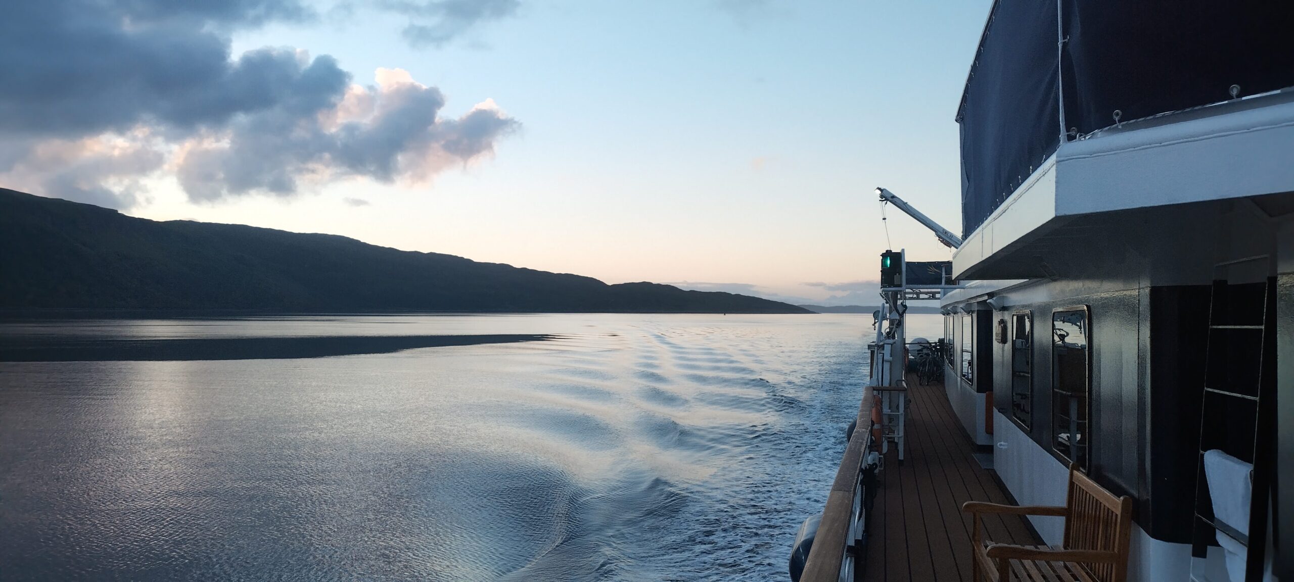
First of all though, I must give you an update on my work life. Keeping it short, and without telling too many tales, I found that Lord of the Glens was not going to be a good fit for me, despite a nice rotation and the prospect of winter to do other things (actually this could be deemed a negative aspect rather than positive). The first 4-week trip of the cruising season did not go well, and I promised myself I’d wait until the end of the second trip before doing anything rash. By the end of the third week it was clear that I would be starting to look elsewhere, and by the time I paid off I had been offered one interview for my first morning at home. As well as this, on the very day I left LOTG, I received an email from a company in Germany called OS Energy. They are the part-owners and managing company for the UK-flagged research and survey vessel Prince Madog, the other part owners being Bangor University, and I had applied to them for the master’s job about this time last year. Unfortunately at this stage it was just a temporary position, which didn’t interest me, so they said they’d keep my details on file in case any longer term prospects came up. They kept their word, and emailed me asking if I was still interested, which of course I was, especially after the couple of months I had had on LOTG. Thus I had two interviews in the first two days of my leave. The first one was for the brigantine Eye of the Wind, which has the advantage of being a tall ship, but carries with it the disadvantages of low pay and long trips; the second with OS Energy. Both resulted in job offers, the Eye though not able to offer me anything starting before March next year, but scheduling a trial trip this season to see if we suit each other. In the meantime, Prince Madog was an immediate start (well, in late July), with a 4 week on, 4-off rotation, and the best salary I’ve had so far. I took this as providential and accepted. I am therefore writing this in the Master’s cabin of Madog, alongside in Cuxhaven after a hectic couple of days’ handover with the other Master whilst underway from Sassnitz on the Baltic coast, via the Kiel (not Caledonian, which I nearly wrote out of habit) Canal. These days she does quite a lot of work in Germany, given the location of the company, and has been working around the windfarms in the German Bight and Baltic for the last few weeks. There will be some academic work with a German university in September, then I understand she will return to her “home” base in Menai Bridge for the UK university term in October. Much of the commercial work is of a confidential nature and therefore I can’t divulge too much or take photos, but it sounds quite interesting and should keep me busy from a shiphandling point of view.

Right, back to the real job of finishing Serchthrift before I’m old and grey. Masts. As you may recall, about this time last year I enlisted the assistance of Louis to help me build my foremast – a hollow mast built on the birdsmouth principal, and sheathed with glass and epoxy. In addition to this, even longer ago you may also recall I had bought a second-hand mast for my mainmast from a fellow junkie Pol, who as a sawyer also supplied me with the Douglas Fir for the foremast. This mast is solid Douglas Fir, and was purchased in the knowledge that it was 40cm shorter than required for my rig. I have thought long and hard about how to go about lengthening the mast to fit, and the original plan was to essentially scarph on another chunk to the foot of the mast, which would have been hard work and would also have involved a lot of wastage in timber. As built however, the mast had a 45cm length at the head which had been planed to a smaller diameter so the masthead fitting sat at the right height for the previous boat’s rig. This lent itself quite nicely to the addition of a short length of aluminium tube to the masthead to bring it to the correct final length, so that is what I decided to do.
Before it came to that stage, however, there were a couple of other fairly major jobs to undertake. Firstly, the mast being solid meant that there was no natural channel up the centre for cables to be run for lights and antennae. Pol had obviously not worried about this, and kept his masthead unencumbered with such frivolities. I, however, wanted my VHF aerial to be at height, as well as having a steaming light and deck flood up there. I had to therefore devise a method of running cables where they would not be snagged by the sail, battens, parrels and other such stuff (there will inevitably be much, much more mention of such things in due course, when I get onto rigging and sailing her!). As with any problem like this, I took the step of referring to the bible, otherwise known as Practical Junk Rig (PJR) by Blondie Haslar and Jock McLeod. The recommendation for running cables up solid timber masts is to cut a fairly shallow channel up the mast, lay the cables into it and then glue in a timber spline to fill the remaining space, finally planing it smooth so it is almost invisible. Another, somewhat more drastic, method might have been to slice the mast in half, cut out some of the “meat” in the centre and glueing the halves back together, effectively making it a hollow mast. This would have the added advantage of some weight loss (for ’tis a weighty thing), but trying to make that cut at all accurately with the equipment to hand would have been impossible. Given a chainsaw and guide, with the requisite skills, it may have been possible, but it was not a job I wanted to undertake! Cutting a channel it would be, therefore, and so after some head-scratching I came up with a workable method using my big router.
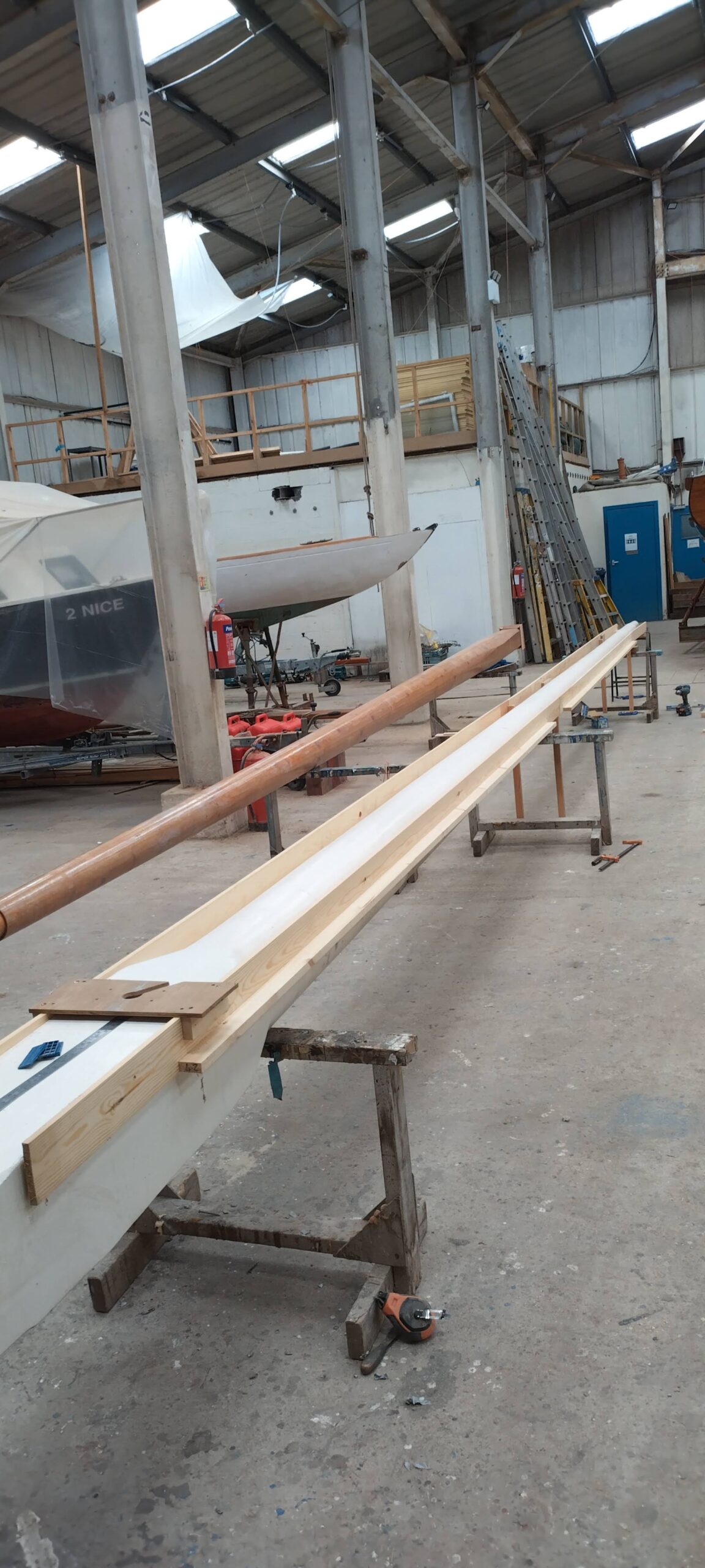
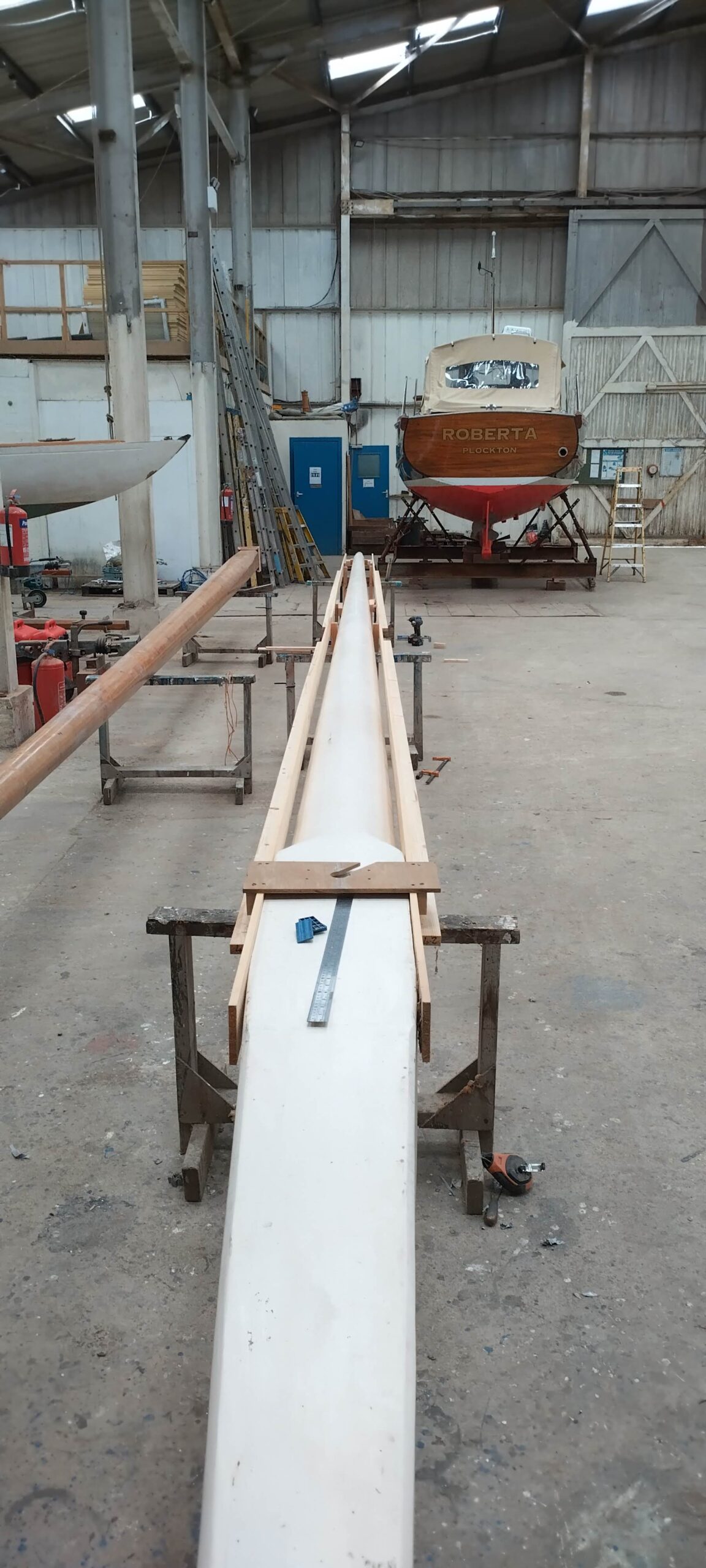
A router, particularly a big powerful one, is not an easy thing to control, particularly on a surface which is increasingly convex as the mast diameter decreases, and a relatively straight and true channel would be required so that a spline could be fitted in with minimal tolerance; therefore some sort of guide or jig would be required. As it happens, I already had a sled available, which was made to fit the scarphing jig I made for joining the foremast staves to make up the required length. With a little adjustment and ingenuity this could be made to run along a pair of rails for the length of the mast, keeping it straight and level. With some of the long pieces of softwood ceiling planking and carcassing in my timber stock, and screwing directly into the mast with spacer blocks as required, the rails started to take shape. It was clear initially that the thin 12mm planks were very flimsy and would not stay a constant distance apart or indeed remain straight without some longitudinal reinforcement. This is where the carcassing came in, screwing bits of 2×1 on edge to the backs of the planks to make them less wibbly (a technical term, I think you’ll find). This helped a lot, and a couple of test runs down with the router on its sled, but without a bit or power, with subsequent adjustment, and it seemed to be ready to give it a try. So gingerly I started my first run, using a 13mm diameter straight bit, and before I’d gone too far the router began to stray off the top centreline of the mast. This was partly still-too-wibbly rails, and partly because, in adjusting my body position during the run I had inadvertently altered the pressure applied to one side of the router. I added a few more spacer blocks between the rails and the mast, and tried again. The full depth of the channel should not be attempted in one run, mainly for the well-being of the router motor and bit, so the first run was maybe 2-3mm deep, and the slight diversion therefore was not too critical and would ultimately be made good with some epoxy filler. The second run went much better, and I managed a full length channel a few millimetres deep, with not too much wiggling. The tracks were still slightly flexible, so a steady hand and good control of the router were required, as well as kicking the extension lead reel gently along in front of me as I walked along with the router so it would not snag on the trestles and pull me off course! It would have been dead handy at this point to have had an assistant walking alongside me with the reel in hand and making sure the cable did not snag, but such a luxury was not available. I continued with care, each run increasing the depth by a couple of millimetres until I had reached a final depth of about 12-15mm.
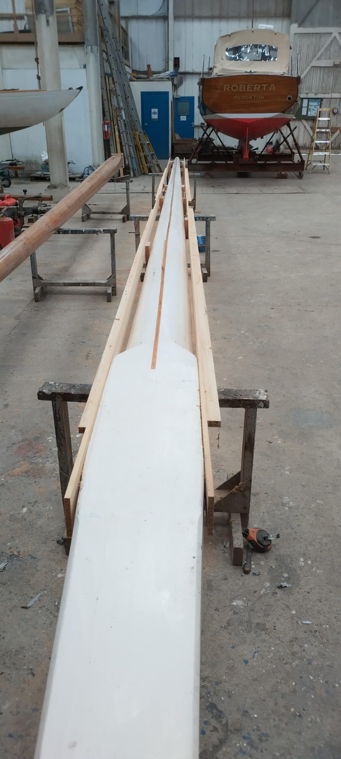
That was the difficult bit done. I then coated the inside of the channel with a couple of good coats of epoxy resin, and in the meantime prepared my spline, using a length of the planed Douglas Fir I had left over from the cabin sole beams. I cut it roughly to the right dimensions with the table saw, and then passed it through the thicknesser a few times to get it down to a width which would be a tightish fit into the channel. As these lengths were about 5m, I needed to cut scarphs in the ends of each length in order to give a nice contiguous spline with no sudden breaks – for this I used my scarphing jig, which was perhaps a bit big for the job, but it did the trick.
Before glueing the splines in, I needed to lay in the cables, and initially in doing so I tried to address an issue I had identified with using this method. This issue is that, in glueing in a spline, one is most probably also glueing the cables in place so they cannot be easily replaced should corrosion occur in the cores (a particular problem with coaxial antenna cable, which wicks moisture). I tried laying in a polythene liner over the cables, to which epoxy glue would not adhere and which might allow a firmly-pulled cable to slide out of the channel. However, this was like wrestling with extremely slippery and long eels, and the strips of plastic just would not stay in the channel! After an hour or so trying, I gave up, and decided I would just leave plenty of spare at each end of the cables to cut and shorten back to good core if corrosion became an issue in the future. Fortunately this can be stowed / concealed at either end: under the sole boards at the mast foot, and inside the hollow aluminium masthead fitting, and pulled out as required. This decision made, I gave the glueing faces of the splines a coat of raw resin before applied thickened epoxy glue and pressing the spline in to the channel along its whole length, mating the scarphs as I went, and using cable ties to hold it in where it was a bit looser (now lubricated with glue of course!) and didn’t hold itself in place, or where the weight of the cables was pulling it upwards.
This was all left to cure overnight, and then the excess spline was planed off and sanded smooth with the rest of the mast, producing a very pleasing result. There were a few small irregularities (including the “siding” created from the deviation of the router on my first run) and screw holes which were filled with low density epoxy filler and again sanded smooth.
This led me to the second major job on this mast. As bought, the mast foot ended in a square section, and the dimension diagonally across this section at its widest point was too large for the mast to fit into the steel collar of my mast partners. To resolve this, I needed to plane this part of the mast to an octagonal section, or to “eight-side” it, in mastmaking parlance. This did not need to be super-accurate, as it had no structural importance, but of course needs to look sweet to the eye when sitting in the saloon by lamplight with a tot or a dram in hand. I used a bit of simple maths to establish the widths of each of the eight sides at various points along the taper – making it easier on myself by not making the sides equal all the way down, but the planed faces would get narrower as they got closer to the foot – and marked them out as straight lines along the section of mast. Out came the electric planer, and it was a fairly quick job to plane them down to the required width, so that at the very foot of the mast the new faces tapered to a point and the final couple of inches remained the original square section. The reason for this leads us to the next stage of the job: the mast foot was too small for the steel mast step socket I had welded into the keel some years before I bought the mast. As I knew that the mast would be in and out of the boat many times over its lifetime, and Douglas Fir not being the most resilient timber when it comes both to knocks and bumps, but also to water absorption and swelling, I used some handy pieces of iroko (lab worktop again!) and glued them on each of the four faces. Once the glue had cured, I used a light plywood jig which I had made from a template taken from the mast step firstly to cut the mast foot to the right angle (the top plate of the keel is not square to the mast) and then to plane and shape the iroko blocks to fit the jig with minimal room to spare, but equally some space for swelling! I had made a similar jig for the foremast, so now also checked the dimensions of its foot, and other than adjusting the angle slightly, prove it to fit quite nicely. I bevelled all the edges of the parts which would slot into the steps on both masts, to allow for the welds in the corners of the steel structure, and finally cut a suitably-sized circular recess in each mastfoot into which the mast coins were glued. For the mainmast I had bought a brand-new, shiny £2 coin from the Royal Mint, a special edition depicting Captain Scott’s RRS Discovery, which I thought appropriate both to my square-rig heritage and polar pretensions. For the foremast I had picked out from my Mum’s collection of old shrapnel a Greek drachma coin depicting a square-rigged ship – this one of course referring to my Greek heritage. These were glued in place, “tails” down so the ships were visible, so they could not be lost! Lastly, I bored the holes fore-and-aft through the feet of both masts, using my plywood jigs again, to take the stainless steel pins which will keep them in their steps should Serchthrift decide to do a barrel roll. This was fairly straightforward with the foremast as my auger drill bit was long enough to get through both sides and line up true, whereas in the solid mainmast I had to drill a pilot hole in from both sides with a thinner bit, which wandered off course, but still sort of met in the middle. Once bored out to the full diameter I then had to judiciously employ a round rasp to remove some of the irregularities in the hole so I could get the pin through both the full width of the mast as well as the holes in the jig.
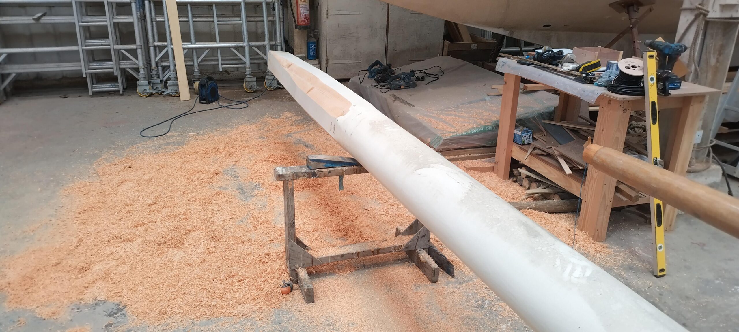
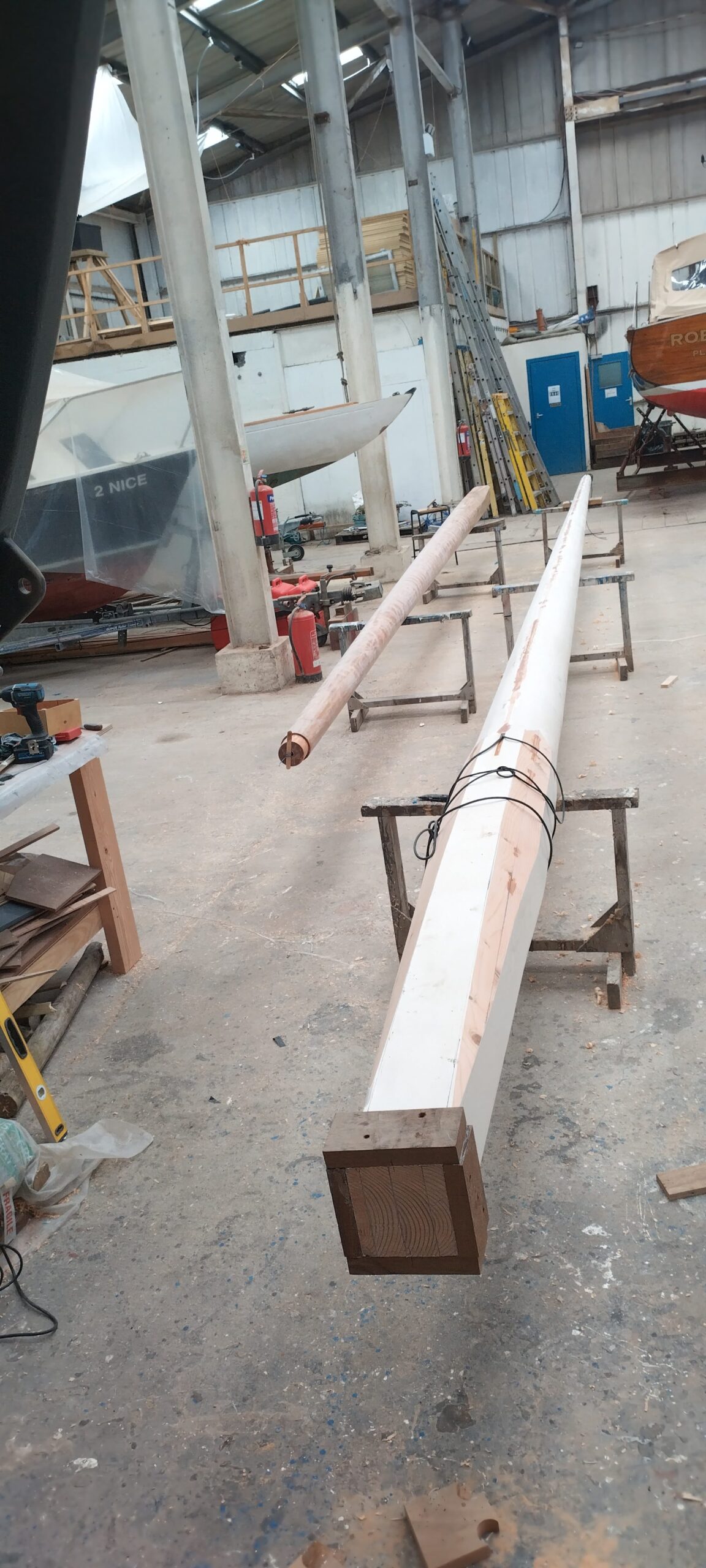
The last structural job before finishing was to ensure that the main mast head would fit the length of aluminium tube I had just had delivered, which would be both the required extension and integral masthead fitting. This required a little judicious planing down to the correct diameter at the “shoulder” on which the tube would be seated, whilst at the very head of the wooden section, I had to glue some spacers to build the diameter up and support the tube for the whole joined section.
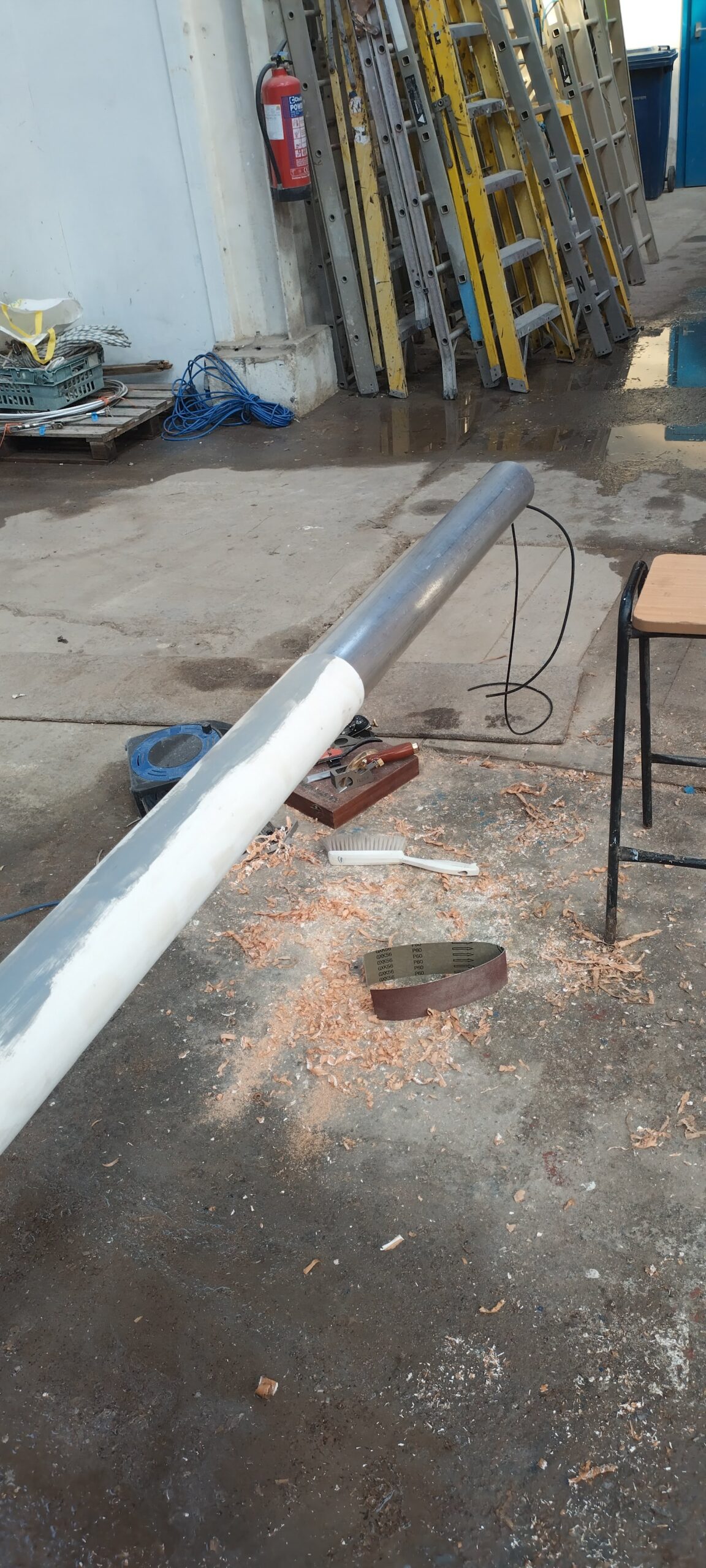
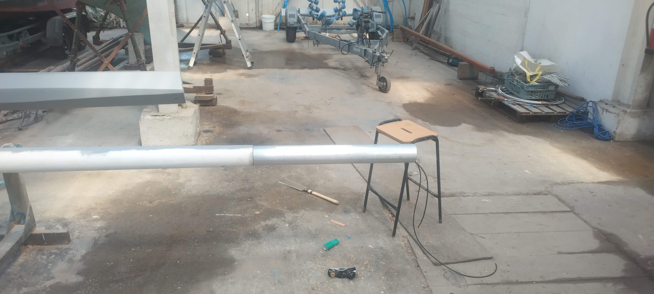
This done, now came the job of finishing both masts. Whilst the mainmast is not epoxy-sheathed, I opted first to coat all the bare wood where I had been working with a couple of coats of epoxy resin before painting. Meanwhile the foremast had been left last year sheathed and well-coated in resin, but with some irregularities in its surface from the weave of the glass cloth. To resolve this, I mixed up a fair quantity of microlight epoxy fairing compound, which was squeegeed over the whole surface and did a passable job of filling all the irregularities bar a couple of small areas which will not be noticeable. This I sanded well (it is, fortunately, a delight to sand) before applying a couple of full coats of epoxy primer. At the same time the mainmast received two patch coats on the bare bits which had already been resin-coated. It was very pleasing at this stage to note that the foremast, despite my seemingly haphazard job of planing it into the round and sanding it, had turned out nice and fair and smooth – dare I say it even better than the mainmast…!
Once both masts had been primed and sanded, I then applied a couple of generous coats of two-part polyurethane top coat, in the same cream colour as the superstructure, and they both look excellent! Once the paint had had time to cure fully, I then called upon some assistance to wheel them both back into the covered mast rack for stowage until the time comes to finally fit the masthead fittings and dress them for stepping! In between top coats, incidentally, I had taken some time off the boat to entertain the Phillips elders and my brother Jim, who had finally managed to reach the far north from his normal habitat in the Canaries. We did the habitual family inspection of the boat of course, and I escaped from hosting duties for a few hours on one of the days to apply the second top coat, but we had a very pleasant few days, with a bit of gardening and some fence / stair handrail rebuilding at home, and a couple of outings including a great boat trip to Iona and Staffa.
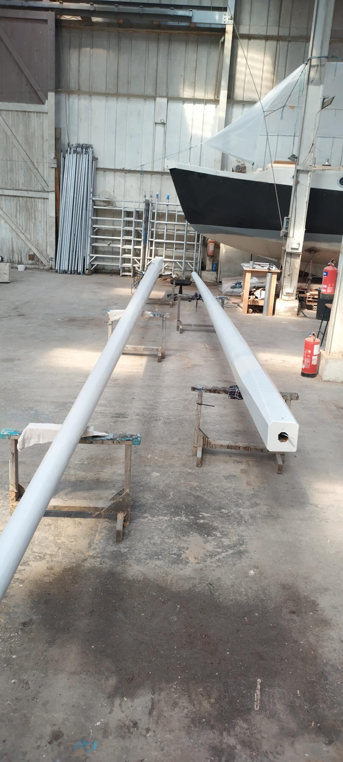
One reason I did not wait before stowing the masts until I had fitted the masthead fittings, other than time, was that the mainmast plus its extension would not fit in the mast rack – it would be about 30cm too long! The other reason of course was that I did not yet have a masthead extension / fitting for the mainmast, and the foremasthead fitting needed a little work before it was itself fitted. As I had a couple of days to spare before I was to join the Madog, I first arranged with Ardfern Yacht Centre to drop the tube and parts I had yet to make for welding (aluminium welding requires more skill than I possess). I then spent one day of the weekend cutting, shaping and drilling the seven lugs which would encircle the masthead as well as a lid from aluminium plate. These were ready for welding for first thing on the Monday morning, to be collected on Wednesday morning before flying out to Germany to join the ship! They did a pretty good job (for a pretty sum of money!), and you can see in the pictures how it looks. This will of course be painted before fitting to the masthead – probably in pure white, as is often seen in traditional boats – it might also help disguise the fact it’s not part of the rest of the mast, nor is it tapered. I will probably also give the top couple of feet of the foremast the same treatment so they match.
Talking of the foremast, my second job for the weekend was welding a lid to the foremast head fitting – this would hopefully stop any water ingress in future and cap off the hollow bit! As this fitting is galvanised steel, I could do this myself, so cut a small piece of 3mm galvy plate to a circle of slightly smaller diameter than the collar of the fitting, then dusted off the welding machine, changed the battery in my welding mask, and did some practice welds on scrap before giving it a go. The first attempt was abortive – I couldn’t seem to make the weld stick to the collar, although it was melting the thinner lid fine. Then I realised the power was set quite low – as the last thing I’d welded was the thin stainless tubing of my pushpit – so I upped the power quite a bit, and hey presto! Successful (albeit a bit messy) welds! These tidied up nicely with the grinder, and after tidying I used spray galvanising paint to patch up where the galvanising had been ground or burnt off.
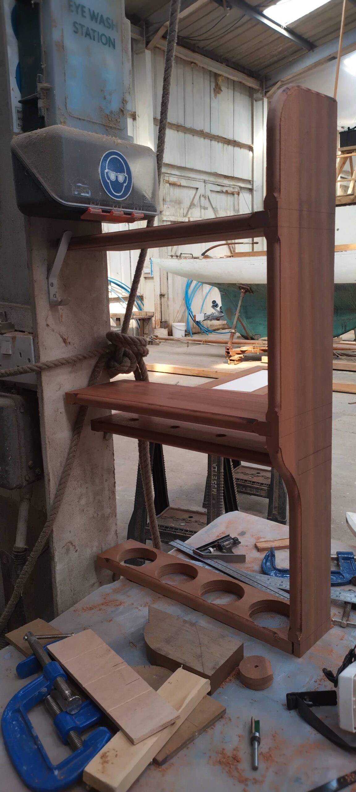
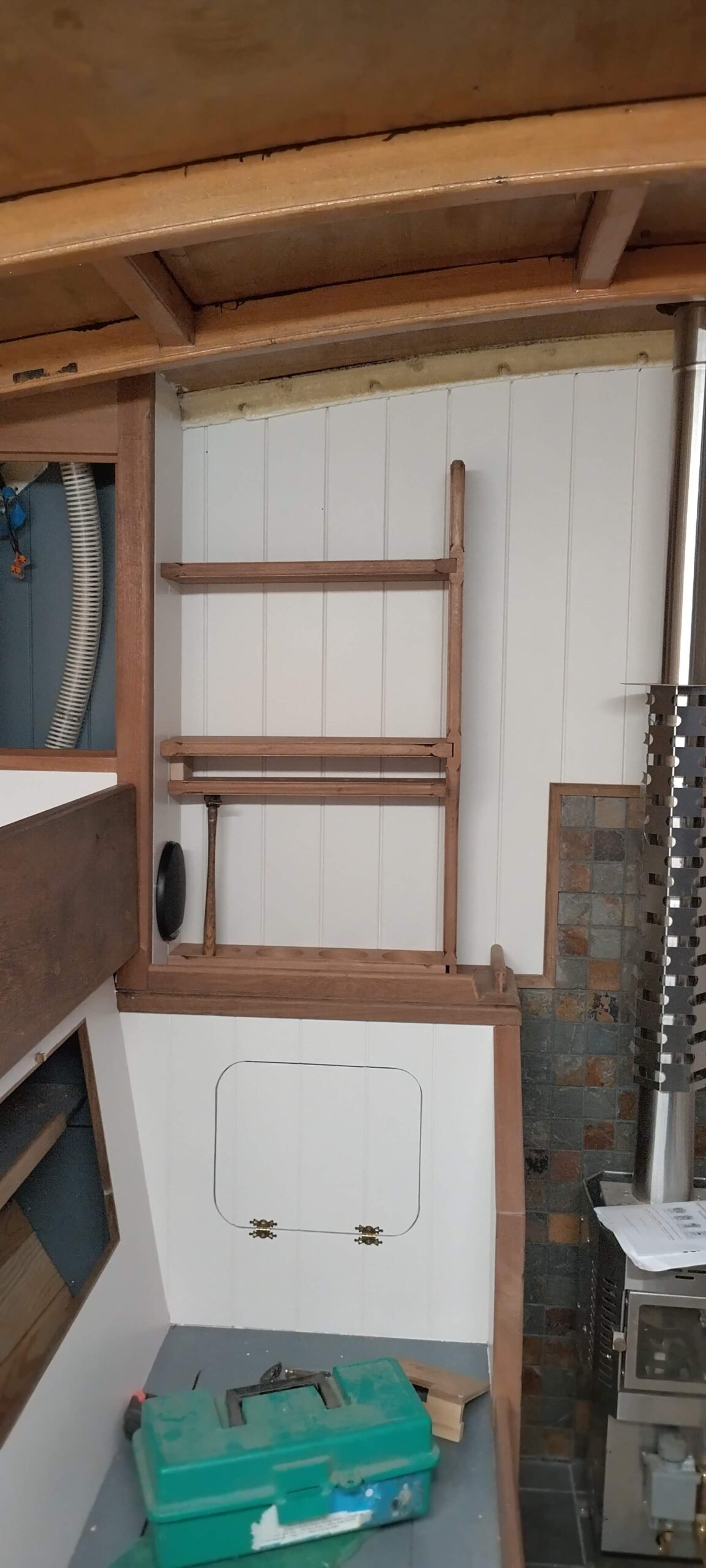
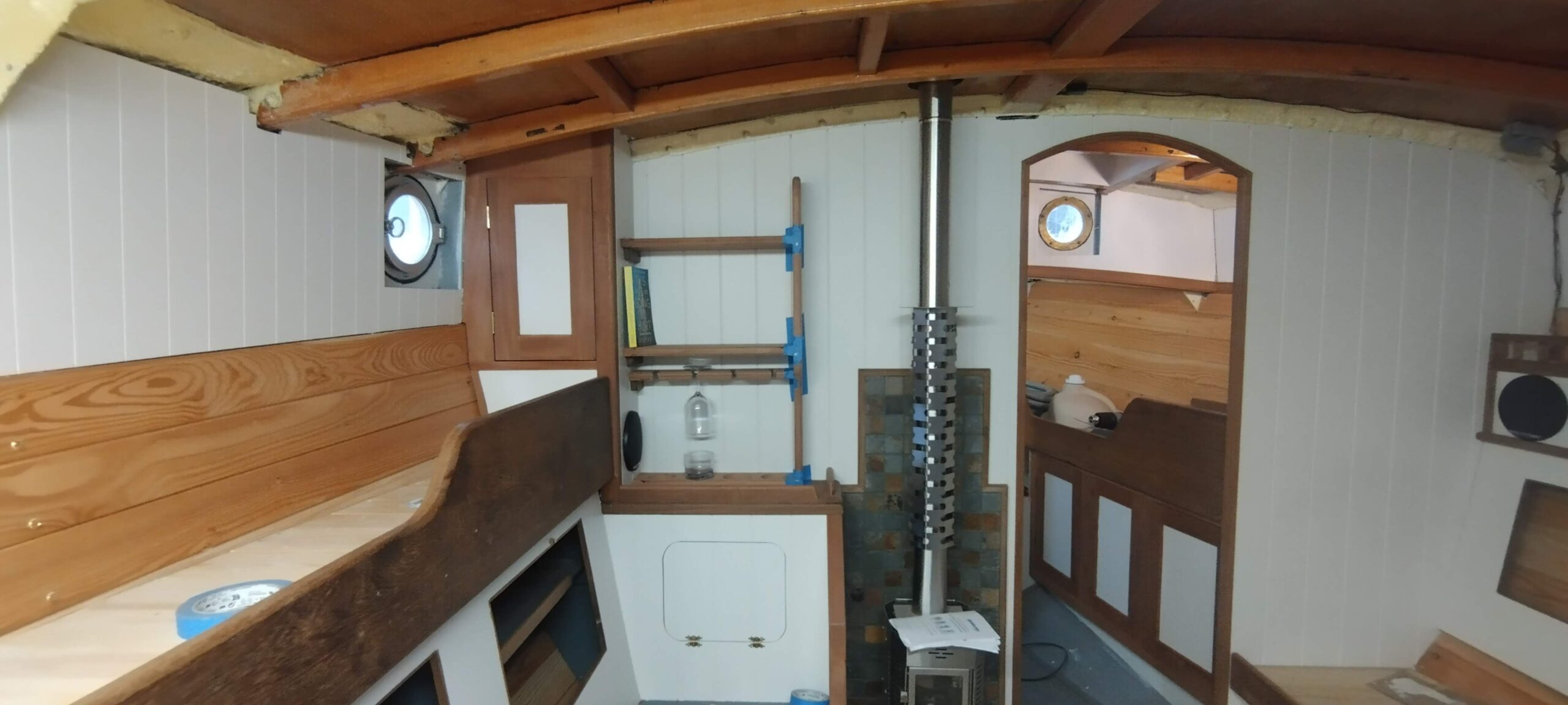
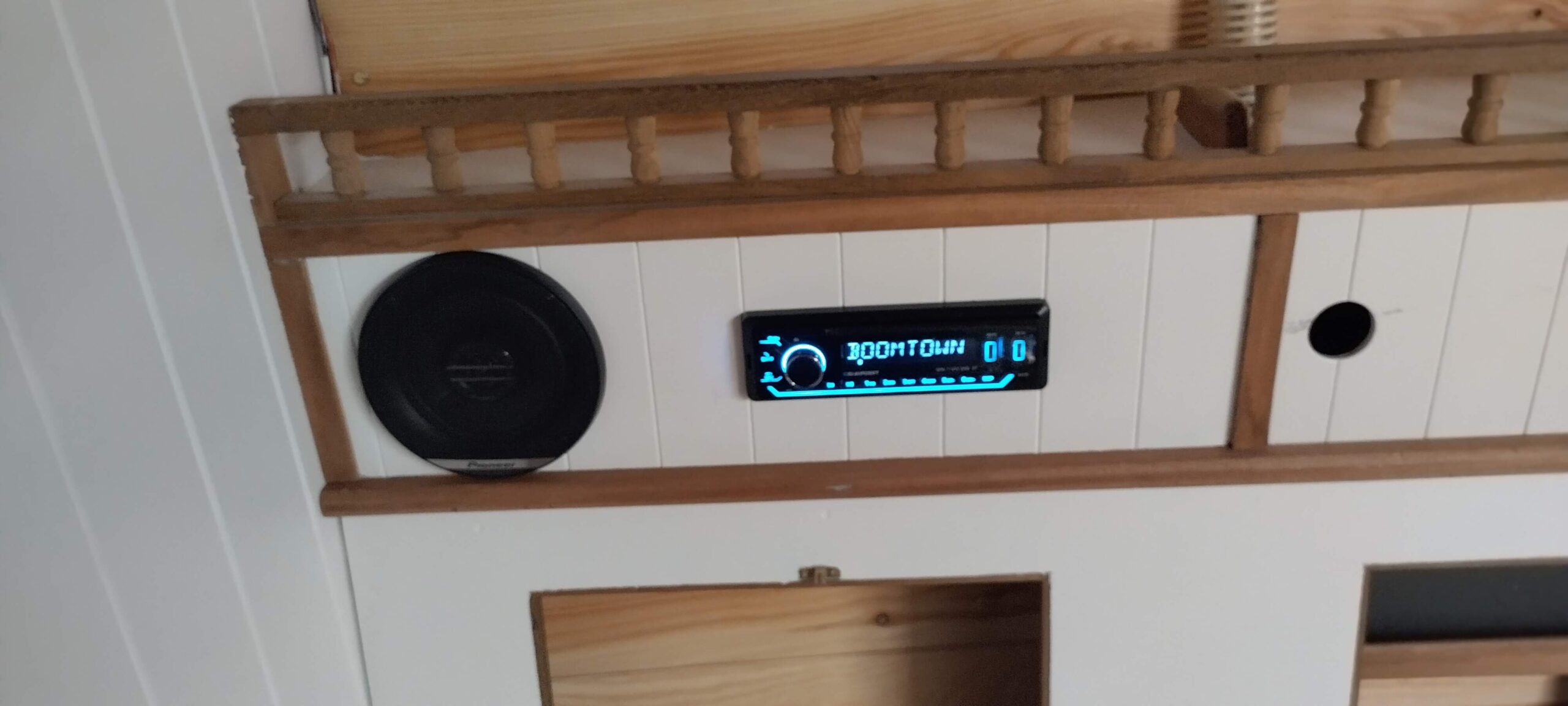
In amongst all the mast work, I had been doing some bits and pieces towards finishing off the saloon as far as possible. This included completing the white paintwork on the panelling, and then fitting the hinged and sliding locker doors. Both required a small amount of adjustment, but now look and work fantastically. Having finished the painting, I also succumbed to the temptation of fitting the stereo and its speakers. The latter fitted nicely into their holes, whilst the rectangular aperture for the stereo itself needed a little trimming before the metal frame could be persuaded to slip in. I connected up the speakers and power at the business end, and then used a short length of two-core cable to wire in the power temporarily to my 12V transformer which also powers the lighting I have so far fitted. Being in a steel boat within a steel shed, the DAB aerial didn’t tune in to any stations, and I have yet to fit an FM aerial (this will come off the main VHF aerial via a splitter), so radio was out of the question. I did however get my phone talking to it over Bluetooth, so now every time I go below, my phone, which is normally singing or chattering away to itself, connects automatically and comes through the boat’s speakers! The last major construction in the saloon which I tackled was the bookshelves and glass rack, which fits above the “sideboard” between the stove and the corner cupboard at the foot of the pilot berth. The design for this was very much in my head (as are many of the structures on board – I didn’t produce any construction drawings as my General Arrangement drawing was rather conceptual and also my ideas keep changing!), but I knew I wanted a couple of shelves for books (of standard paperback size – bigger books are shelved on the starboard side behind the settee). I also wanted a rack for my wine glasses and tumblers, which are polycarbonate, but still look nice. To house all this I chose one of my widest hardwood boards, which are 200mm wide and 20 thick. These would make shelves just wide enough for their paperback load. The outboard ends of the shelves would be supported on blocks screwed into the side panel of the corner cupboard, whilst the inboard ends would be jointed nicely into an upright of the same timber, corners all nicely profiled with the router. Knowing the joint would be highly visible, I needed to be very careful in creating them, so I recommissioned the sled for my table saw, which enables multiple parallel cuts to be made to a set depth to create the “housing” of the joint. The Americans call this kind of slot a Dado, and it is possible to buy a fearsome tool called a Dado blade set for a table saw, which will cut the full slot all in one go to a set depth and width, but I only have a single blade on my saw, so with the workpiece clamped to the sled, several runs can be made across the blade, keeping just inside the lines marking the edges of the housing. With any luck there is minimal waste left in the housing, which can be snapped out by hand, before finishing the sides and bottom of the housing with a router and chisel. This I managed with reasonable success, even managing a “blind” housing (not running the entire width of the board) for the wineglass rack. This rack is of the type where the glass stems slide into slots and sit in a larger diameter hole, hanging upside-down on their bases, so I needed first to drill four holes to fit the stems, then four parallel slots from the edge into the holes, which I did with the bandsaw. The holes were then flared on the top side with a large-ish diameter rounding bit in the router, then all other edges of the slots and the front of the shelves with a smaller diameter rounding bit. The rack for the tumblers was slightly simpler, being four circular holes cut through a board with a holesaw. This would be screwed into the top of the “sideboard”. All the pieces and joints thus cut and shaped, I first dry fitted them to locate the blocks on the outboard side, and then drilled lots of screw holes ready to glue the shelves into the housings in the upright, but all other assembly will be screws only, in order that the furniture can be dismantled in the future in case any hull repairs etc. may be required. This has been my philosophy with the construction of the furniture throughout, so whereas screws might be hidden with plugs or soft filler, the actual structures have been assembled without glue to enable disassembly if needed. Finally I assembled the shelves in situ, using masking tape to avoid glue sticking to where it shouldn’t.
And there I had to finish for this leave – I did the usual tidy-up and sweep around my work areas and headed home to pack.










Wow Chris. Another comprehensive write up. I don’t know how you find the time to write all this up and work on the boat. 😃
I do enjoy reading your reports, so your writing time is not wasted.
To be honest I have to wait until I’m back at work until I can concentrate on writing it all up! I’m so glad you enjoy them – at least I know I have one loyal reader!