
Galley Galore and Main Hatch Hype
I can’t believe that it is already over two weeks since I returned to Prince Madog for my second trip. Where the last trip was on the whole quite quiet, as most of it was spent alongside in Cuxhaven and in drydock, this one started off manic and gradually got worse! My feet barely touched the ground during the first week or so, with a quick transit from Sassnitz to Rostock straight after joining for the next charter, 5 days doing Benthic Surveys in the Fehmarnbelt (Bottom left hand corner of the Baltic) then another quick turnaround and passage through the Canal to Cuxhaven, and on from there into a very rough and unpleasant passage to Menai Bridge (North Wales) to start our period of work with Bangor University. Today was our first day out with the students, and it went well. Another couple of weeks and hopefully I’ll be heading home again.
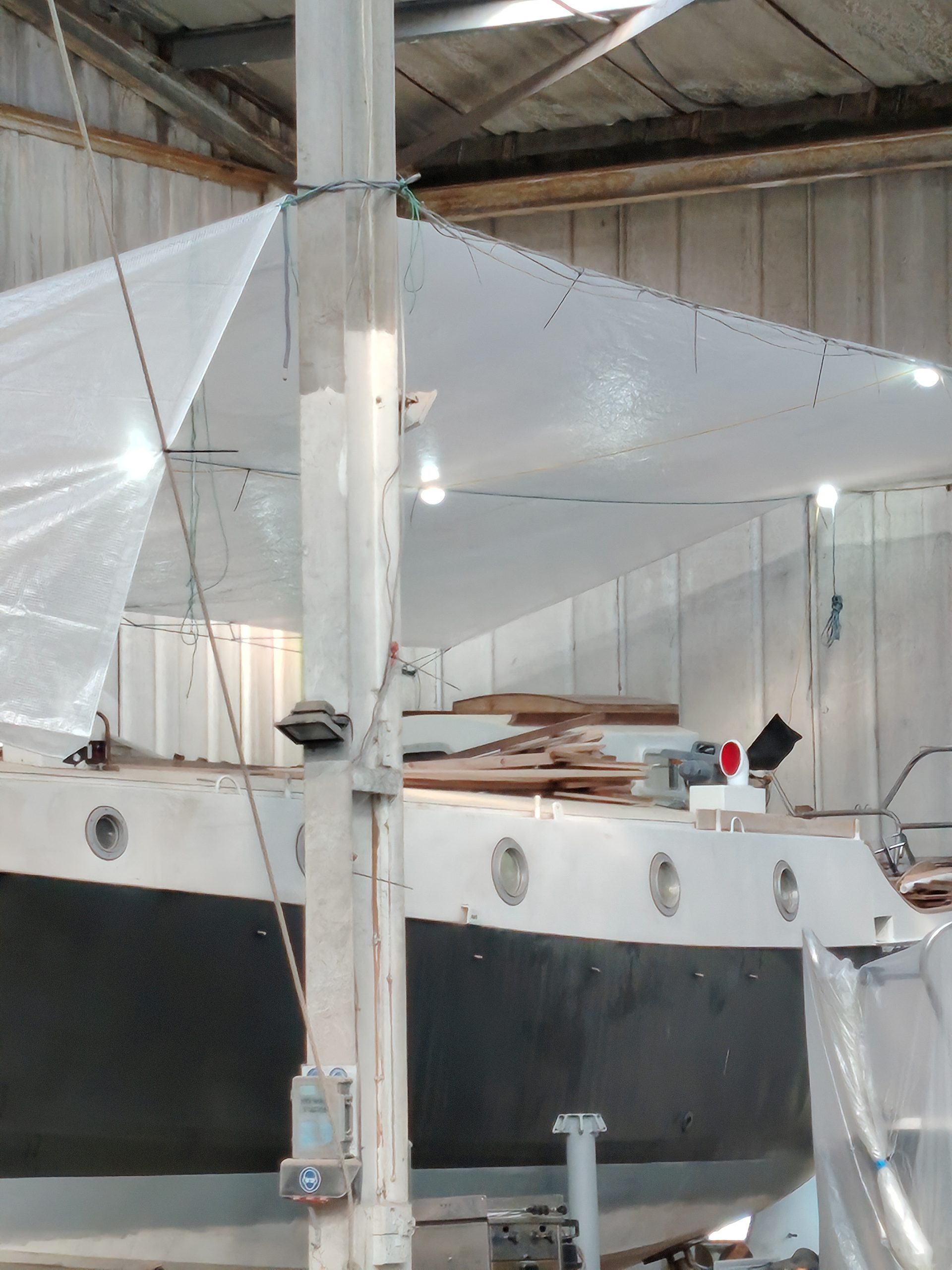
Anyway, I’m not here to write about boring old work, so let’s get back to the boat stuff that I achieved in my last leave period. The focus moved away from the masts again, they both having been stowed back in the mast rack in July. The saloon being more or less complete, the work in the accommodation moved into the galley. Alongside this, the second project was to be starting the construction of my main hatch, whilst temperatures were still warm enough for epoxying.
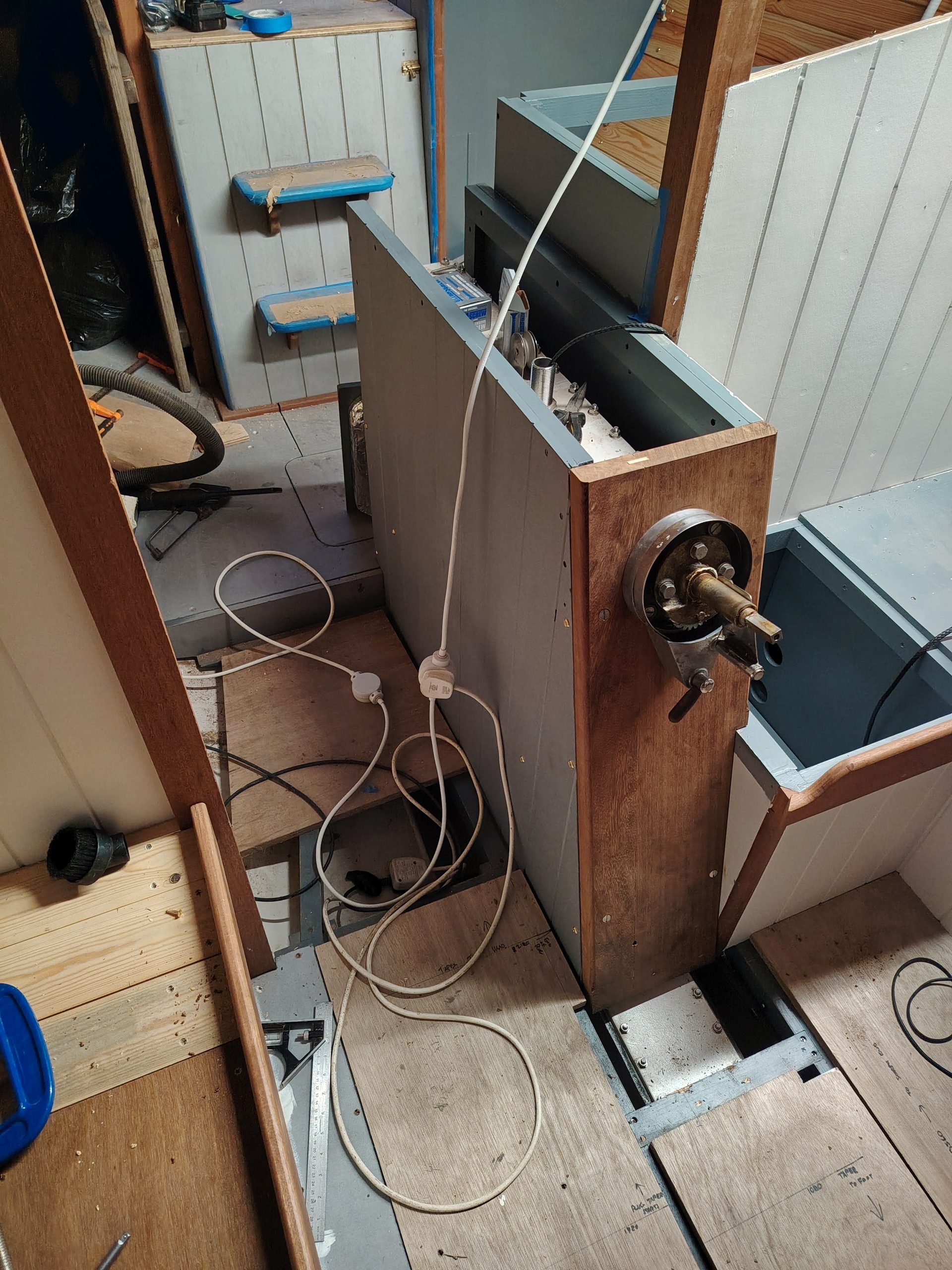
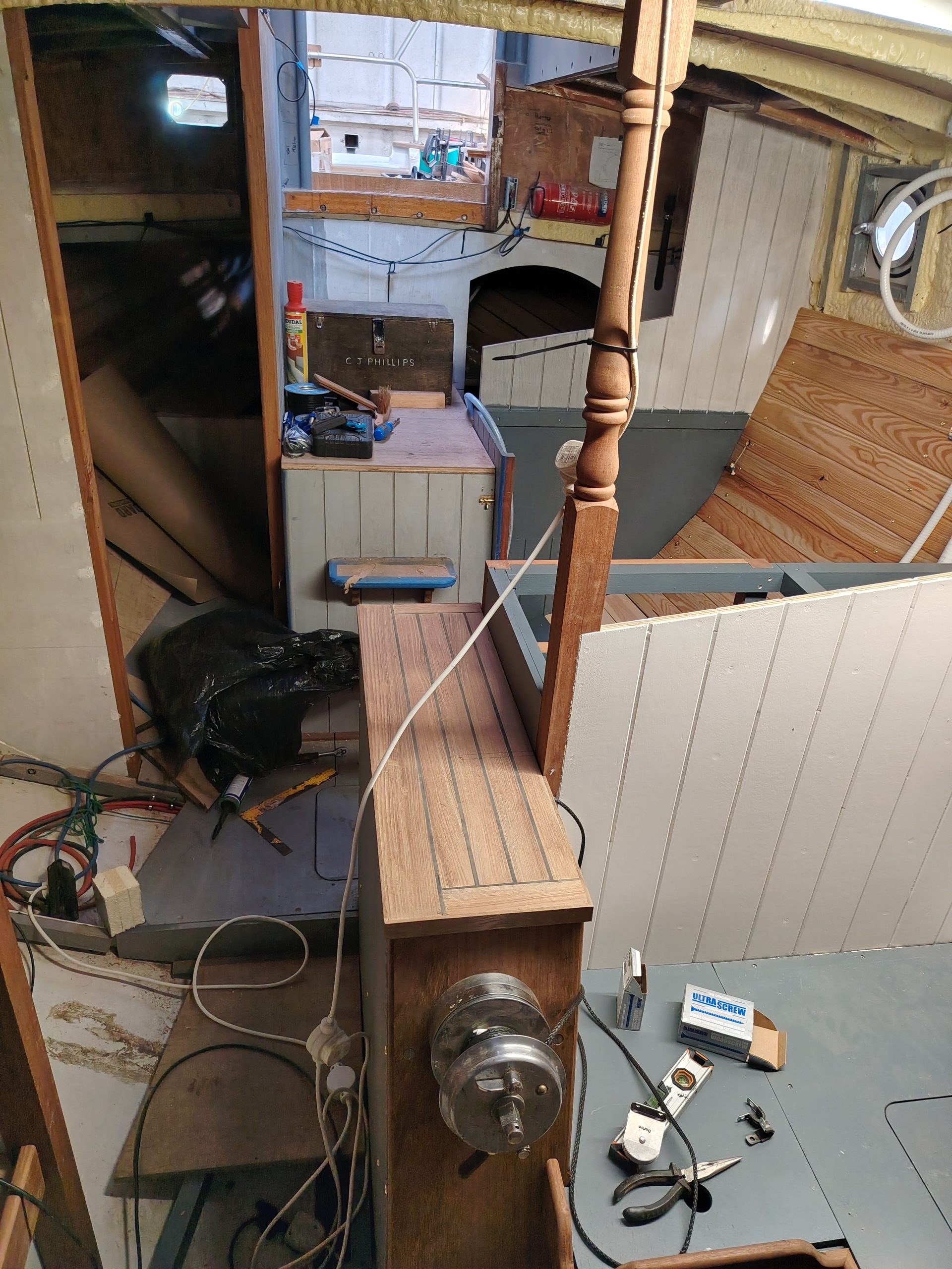
I shall concentrate first on the work in the galley, so we will probably not be going quite in the chronological order of how the entire scope of my work actually happened. First I had to finally decide on what the layout was going to be. I had considered the option of having my cooker athwartships on the forward leg of the “U” shape, facing forward. This worked well in Meander, but not being sure how much Wylos heel, I didn’t want to build it in here and then realise that when sailing it would be unuseable. There were other factors in play too, not least that I needed access through the inboard “wall” of this leg to get to the bolts around the bottom flange of the centreboard case, should this ever need lifting out. I also wanted a good sized fridge and another good sized locker for dry food stores and fruit and veg. These factors pointed me towards having the stove on the fore-and-aft leg of the “U”, gimballed against rolling and heeling. The only flaw in the gimballing plan is that with the galley so far outboard, there is not that much room available for a gimballed stove to swing when heeling / rolling to port, but I figured something is better than nothing, and this is a compromise I am going to have to accept. I still don’t especially trust gimballed stoves, and will probably only want to use the gimbals in extremis. The aft leg of the “U” will be for the sink and a draining area, with fridge compressor, sink plumbing and the stove’s paraffin tank in the locker underneath. Along the hull side at the back of the worktop will be lockers for crockery, coffee & tea making things, and ready-use ingredients. I started with the forward part of the galley cabinetry, which will house the fridge (top-loading) in the outboard half, and a decent-sized dry food locker inboard, topped with a drawer for cutlery and utensils. The inboard “wall” of this cupboard is formed by the centreboard case lining panel, which I had already installed some time ago (remember? – you’re going to be tested on this at the end of the class!). Before getting too stuck in with the galley cabinet therefore I needed to finish off the lining of the centreboard case. This consisted of the starboard side panel, which I cut from 12mm ply with my accustomed fake-tongue-and-groove routed on the visible face. The forward panel needed to be pretty substantial, and similarly fastened to the cleating on the steel centreboard case, as this was to be the mounting for the centreboard winch. I wanted both the forward and aft panels of the case lining to be nice varnished hardwood, so the forward panel was cut from another piece of my reclaimed lab worktop, whilst the aft face was glued up edge-to-edge from two lengths of slightly less substantial 20mm sapele boards. The forward panel was drilled for bolts both to secure it to the centreboard case, and to secure the winch to it, whilst the aft panel was simply screwed in place with brass screws. All these panels (except possibly the forward one) need to be easily removeable in order to allow the centreboard case to be lifted off its flange for maintenance or repairs if required. At this stage I also drilled through the deckhead and fore-and-aft centreline deck stringer (a substantial member of which you don’t often see the like) in order to fit the turning block for the dyneema centreboard line. The final panel to fit to the centreboard case was an infill piece on the galley side to fill the gap between the top cover of the centreboard case and the galley work surface. This was simply a scrap of 12mm ply, screwed into the various adjoining panels and members. It goes without saying that all the new plywood parts receive 2 coats of primer and two coats of locker (garage floor) paint (on the inside faces) before final fitting. The finishing touch to the centreboard case is the top, which was perfectly sized to be able to use the old laid-teak cockpit locker lid that was donated to me by Graeme (who all those years ago escorted us across from Balvicar boatyard in his RIB). This needed to be trimmed to size, and the rather worn and dirty top surface (it had been used in Serchthrift initially as a lid on the old temporary engine box, then later as a temporary sole board) sanded smooth. The edges were trimmed with teak strips made from reclaimed teak decking from Norwegian Trond’s boat (which was in the shed a couple of years ago being re-decked). This is the same teak I hope to use to trim the edges of my finished sole boards. Finally an elongated keyhole shaped slot was cut in it to accommodate the centreboard line on its way up to the deckhead turning block.
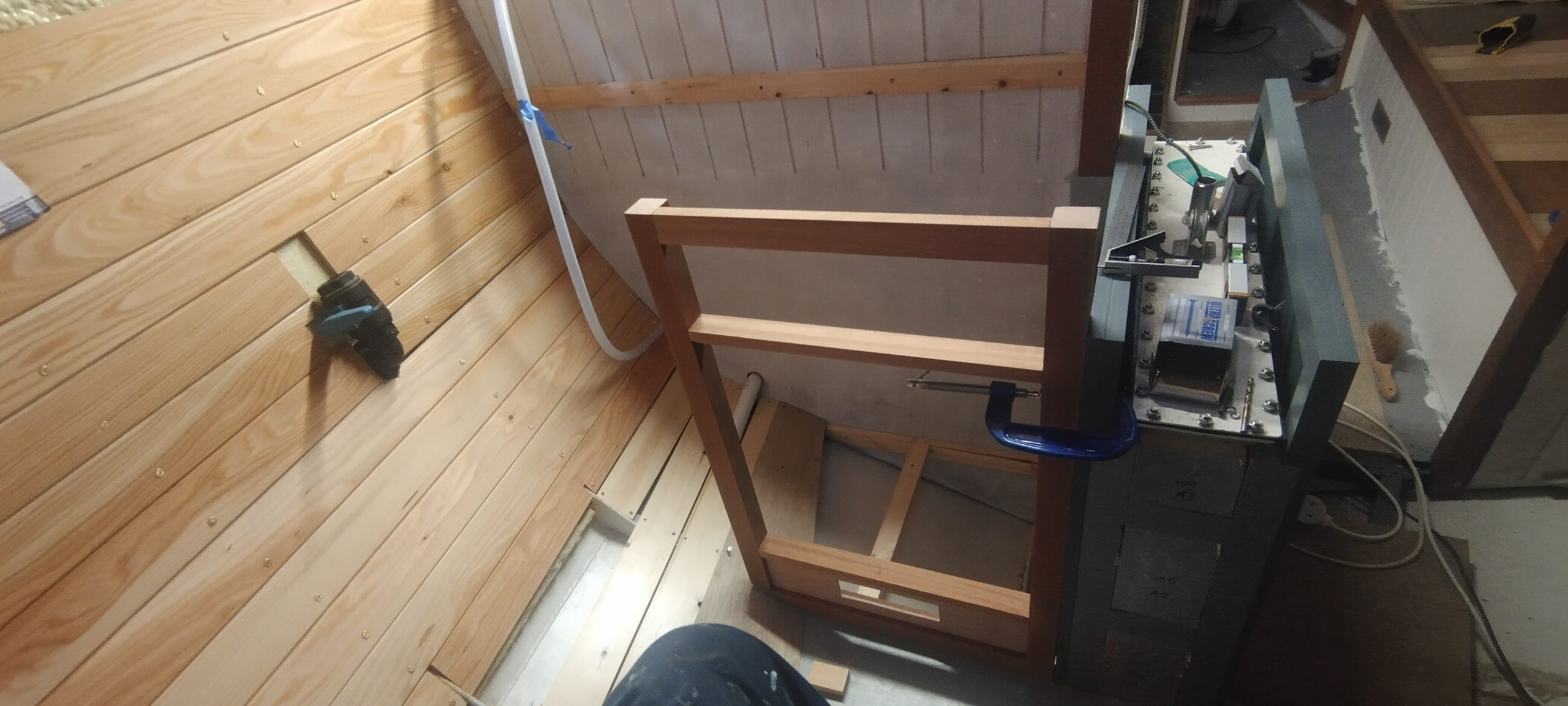
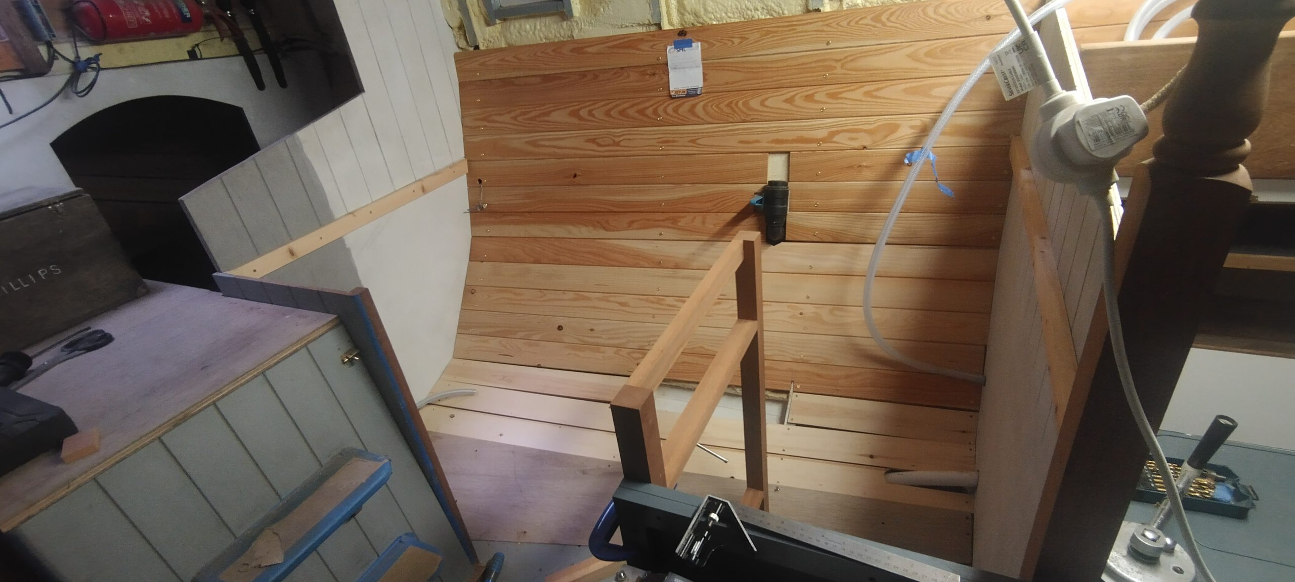
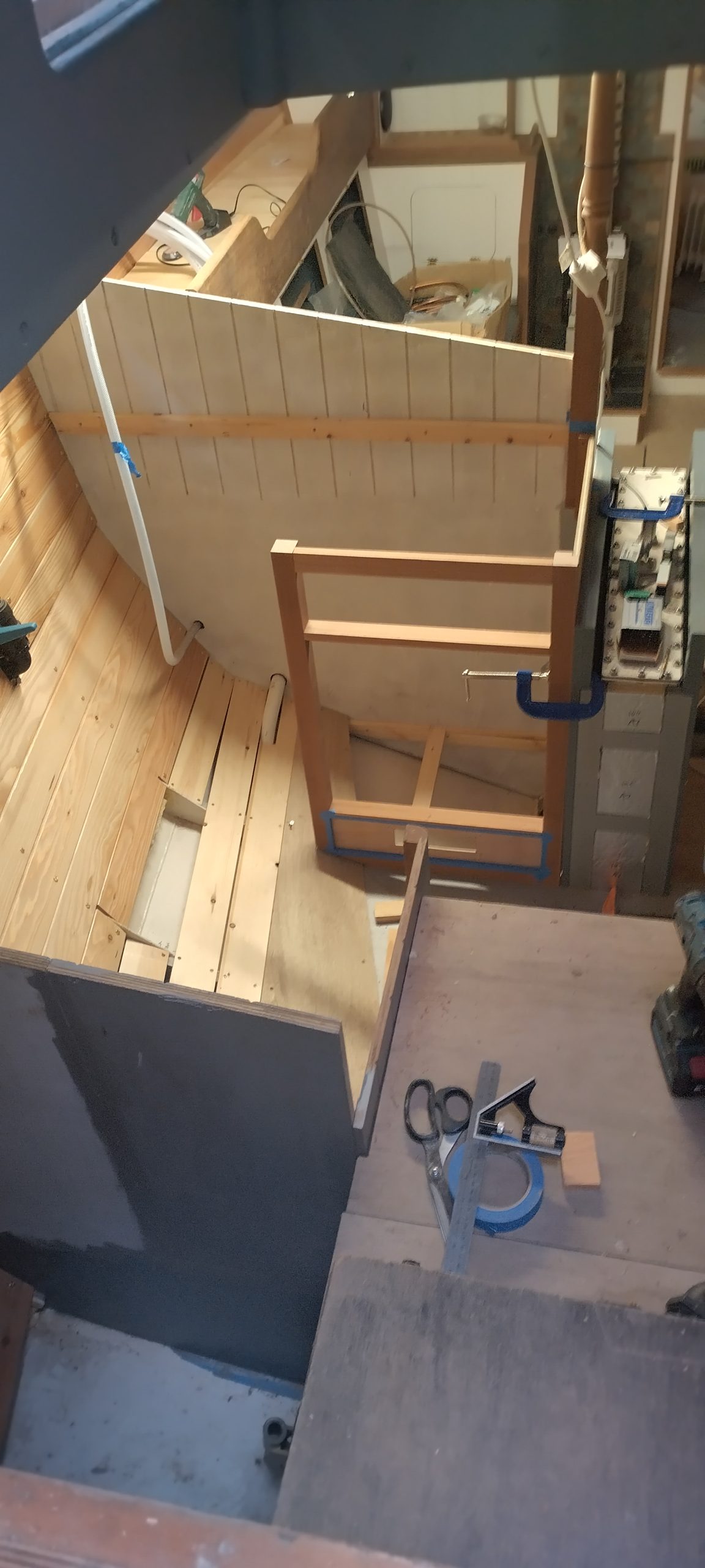
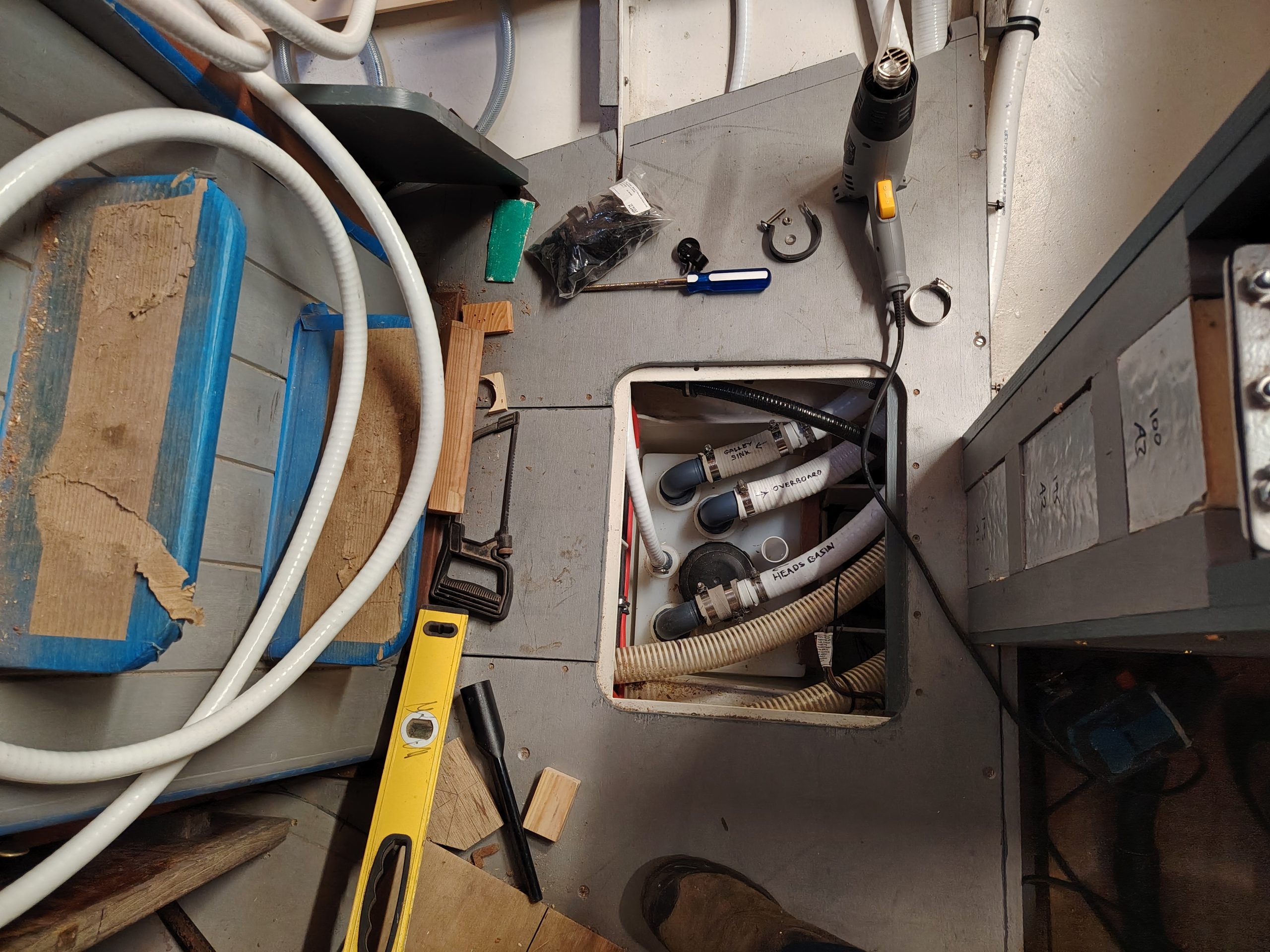
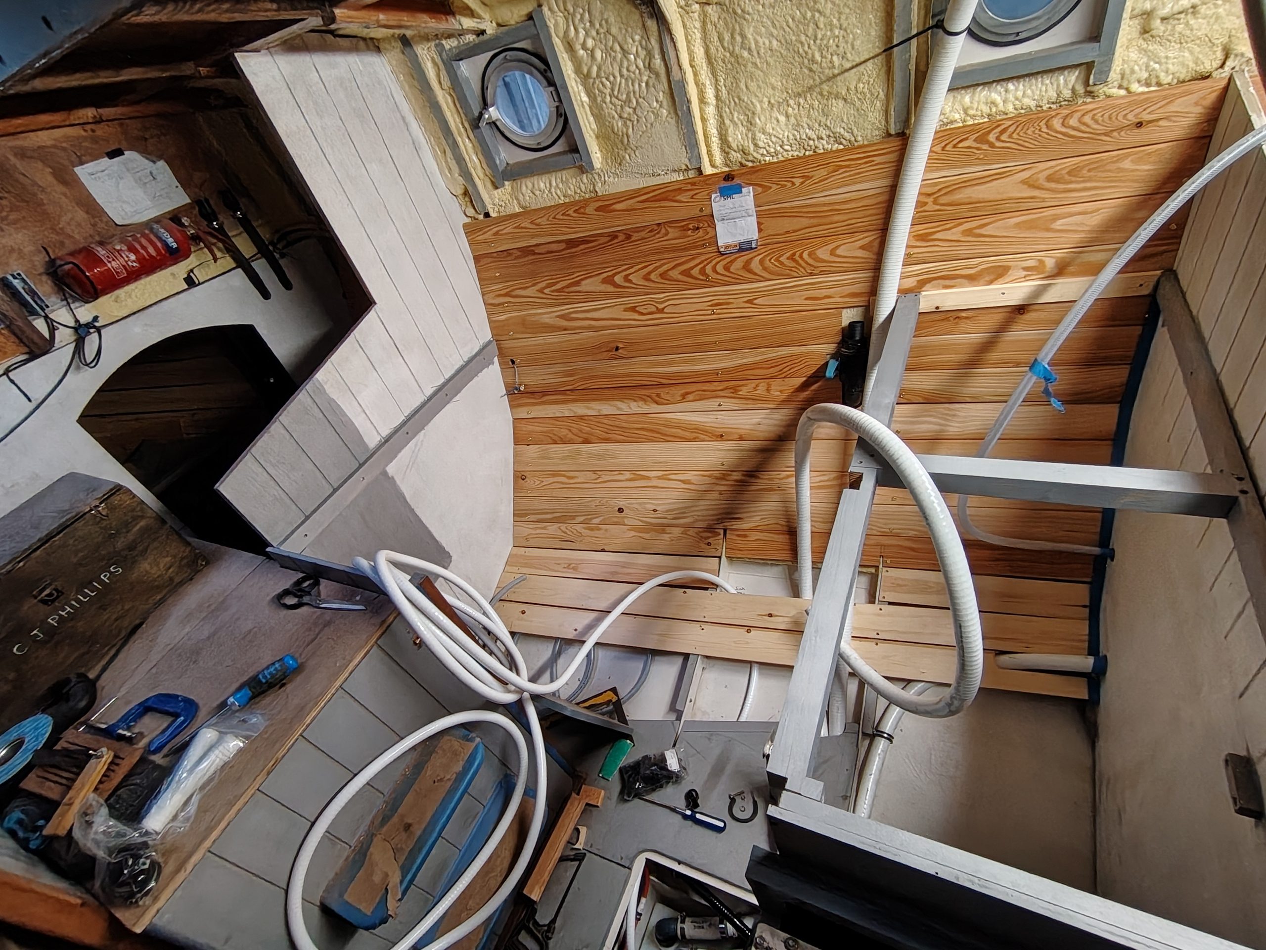
Whilst doing this, I was also lining out the hull side with the usual larch T&G down to the second chine, then softwood ceiling timber for ventilation at the bottom part, and the now customary awkward sloped sole panels adjoining the long-fitted, slightly raised, horizontal sole at the foot of the companionway. These various elements also had to accommodate the plumbing to the sink and also to the grey water tank situated in the bilge sump below the sole. The sump is a focus for plumbing, with 3 bilge pump suction hoses as well as the two drain hoses (heads basin and galley sink), grey water tank vent hose and grey water tank pump-out suction hose, and is quite congested, as you can see in the photo. The grey water hoses all come up into the galley cabinetry, together with the fresh water supply hose from the manifold under the saloon sole, and the port fresh water tank vent hose, which will terminate in a vent on deck just forward of the doghouse. Various holes and gaps had to be cut therefore in the hull lining to allow these hoses to go in their required directions. All in all, this was quite a jigsaw to negotiate and to get right.
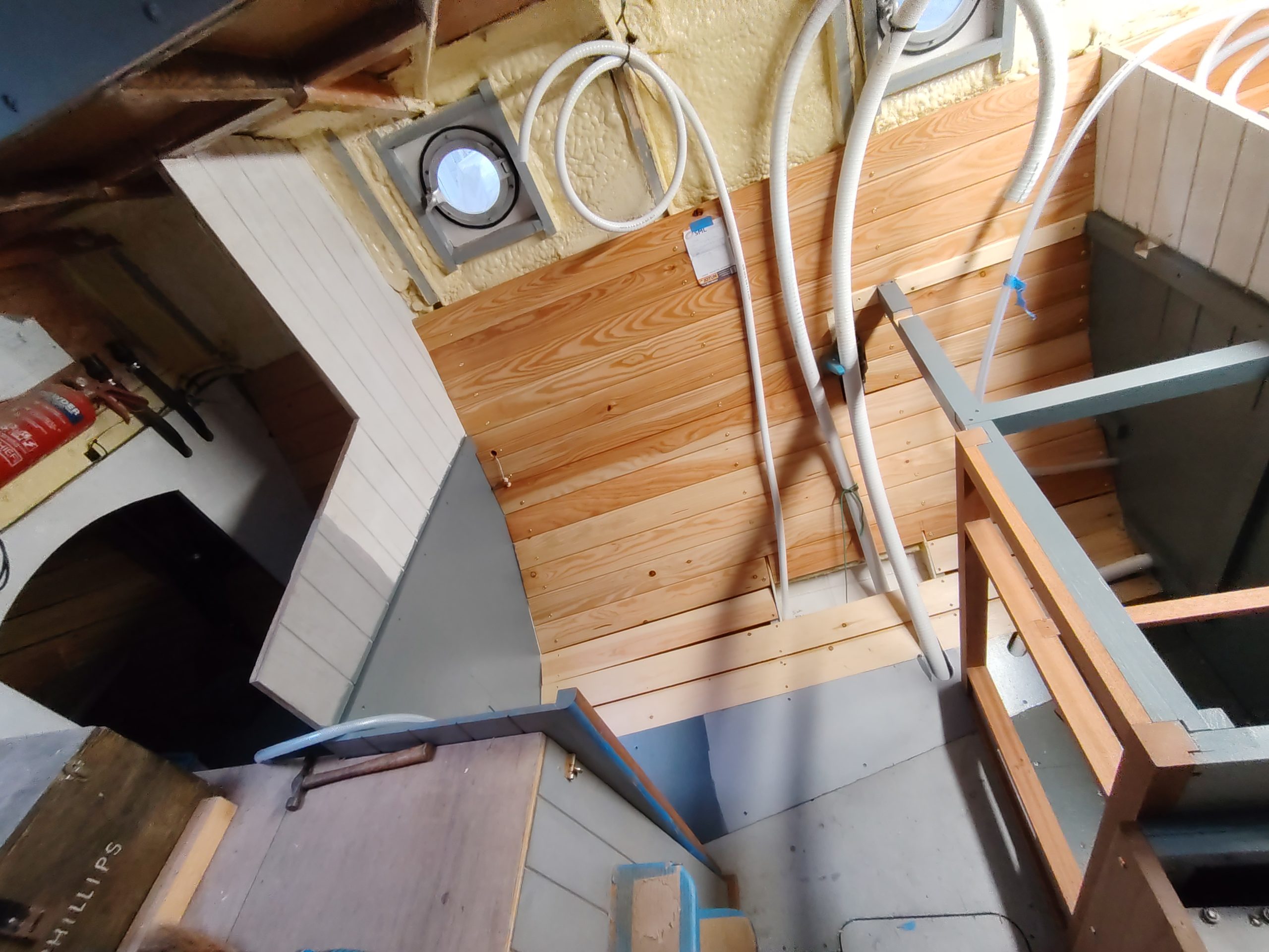
Next to be constructed was the framework for the fridge / larder locker, extending out to the hull side, and incorporating a hardwood frame for the locker door and drawer combination. This frame was constructed in much the same way as the other locker frontages I have already installed, using my dwindling stock of planed sapele 1×2 and 2×2. Below the locker door aperture is a small kick panel with a hole cut for a vent to ensure that the food is well-aired, and also that air can get into the bilge.
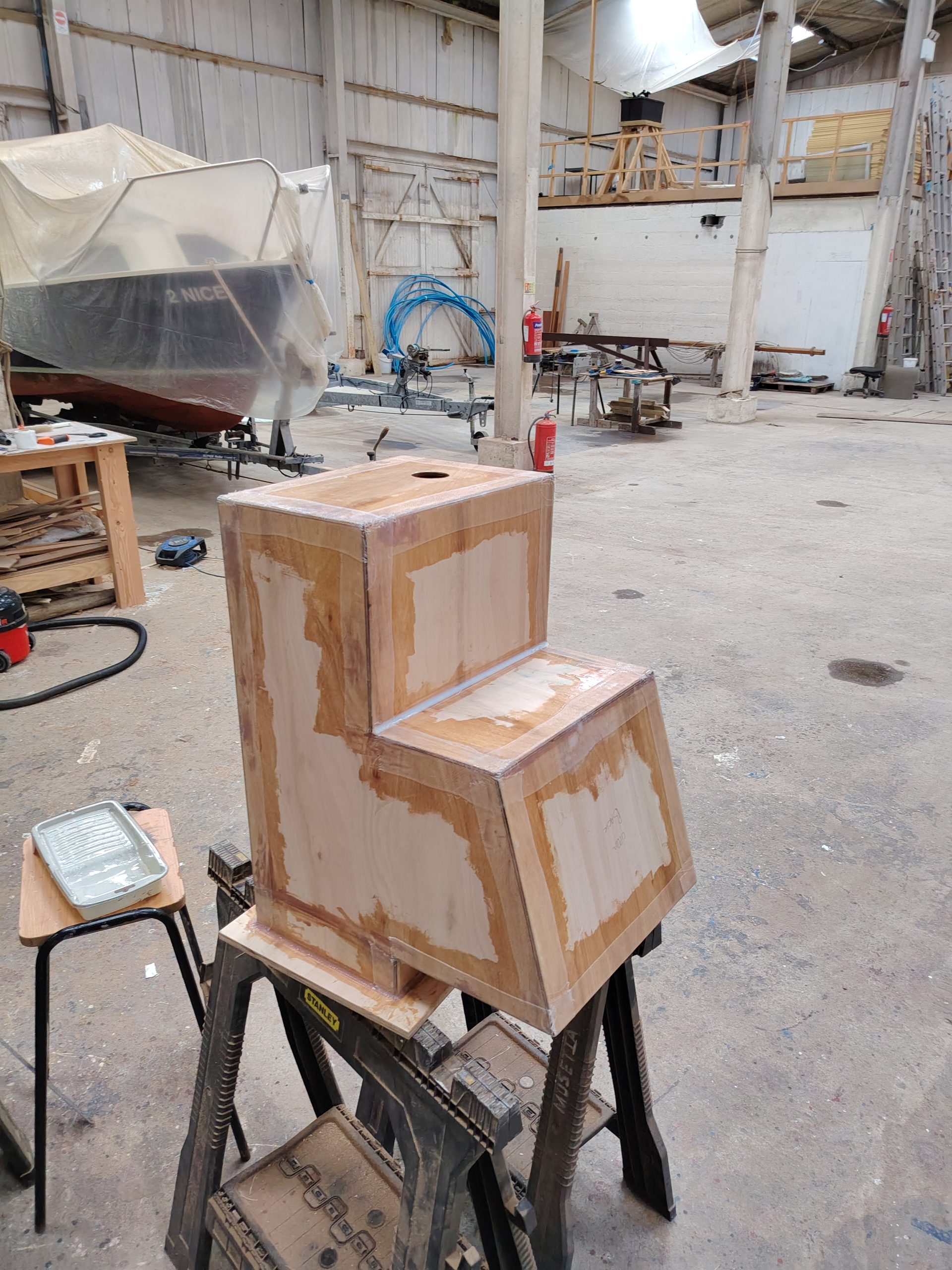
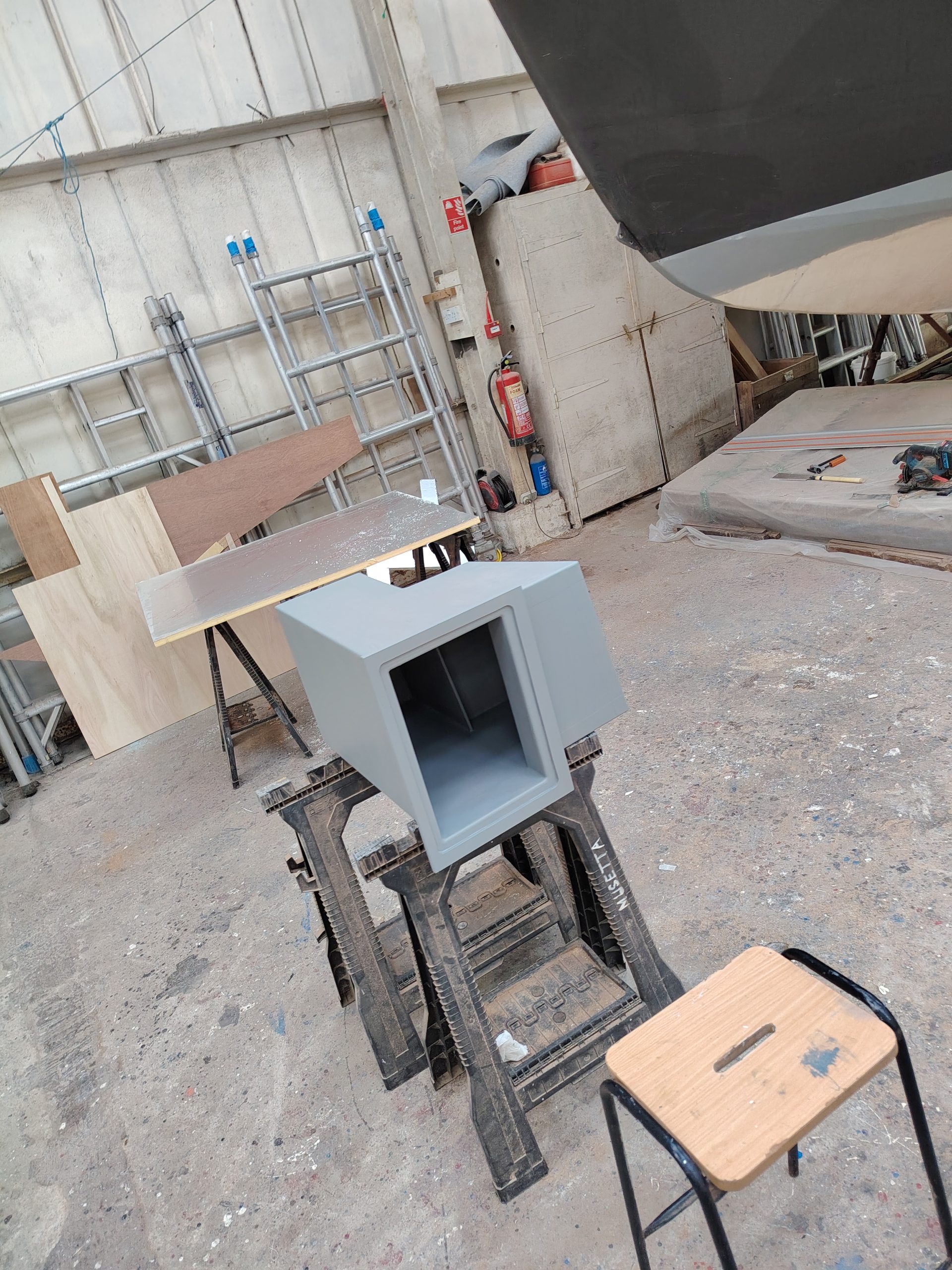
As I have already said, the outboard half of this section of cabinetry will accommodate the fridge, so this had to enclosed with a plywood partition (with access panel at the bottom) between it and the food locker, and another dividing it from what will be the cooker aperture. Some careful measurement and much sketching and head-scratching then took place to design the fridge box itself, which is an inner lining to this section. The requirements here were that it must be sized to accommodate 75mm of insulation all round, and to maximise the available space to give a useable interior volume of fridge. What I ended up with was a box, stepped to fit the hull shape, which means there are two levels for food storage, deep enough for big milk bottles, wine bottles etc., and able to accommodate the “O” section fridge evaporator panel that I wanted (for an ice tray, of course). It is also ever so slightly tapered from forward to aft, again to fit the hull shape. I was as yet undecided how this box was going to be constructed: options were 1) to have a polyurethane box constructed by the same company who made my water tanks; 2) a home-made fibreglass moulding; or 3) an epoxy-ply box. I started out making what I thought was probably going to be a pattern / mock-up for whatever construction I eventually chose, as it is a very complex shape to draw effectively. Using some 6mm ply, I cut all the various panels out oversized, and glued them together with my polyurethane wood glue, keeping everything together using 20x20mm external softwood cleating. I was careful not to glue the cleating itself, but used screws to hold everything whilst the glue went off. So far, so satisfactory. I then removed the cleating, and trimmed all the excess edges off the panels, and it was starting to look like a useable box in itself. So I continued, by adding a double flange around the top access, and then epoxy-filleting all the internal corners of the joints, which had the additional desirable effect of creating nicely wipe-clean internal surfaces with no dirt-traps in the corners. Thus strengthened, I routed / planed / sanded round the external corners. By this time I had decided for sure that this in itself was going to become the actual fridge box. The external corners were all glass taped, and after sanding the whole assembly was given three coats of epoxy resin inside and out. More sanding, and two coats of epoxy primer followed, remembering first to cut a hole in the bottom for the drain! Finally I applied two good coats of two-pack polyurethane gloss white, and the finished box ended up looking remarkably professional.
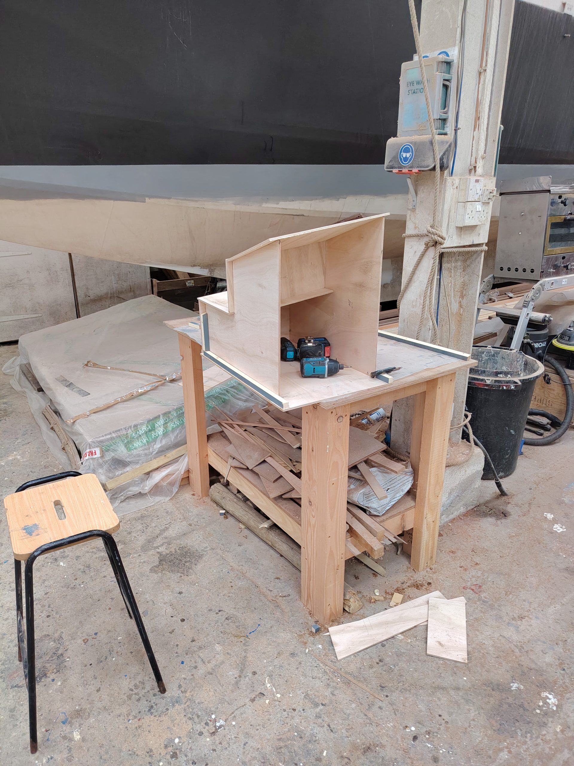
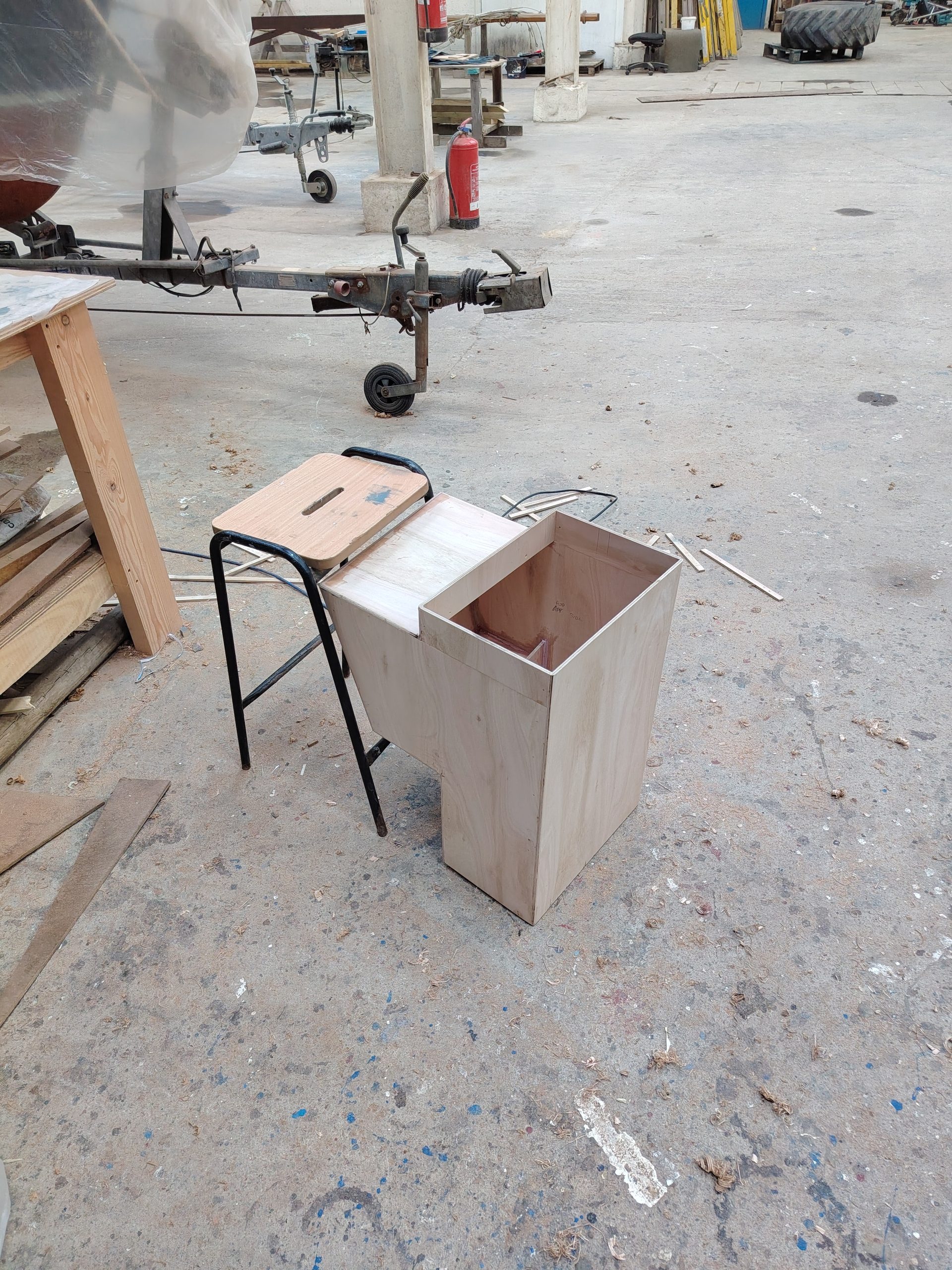
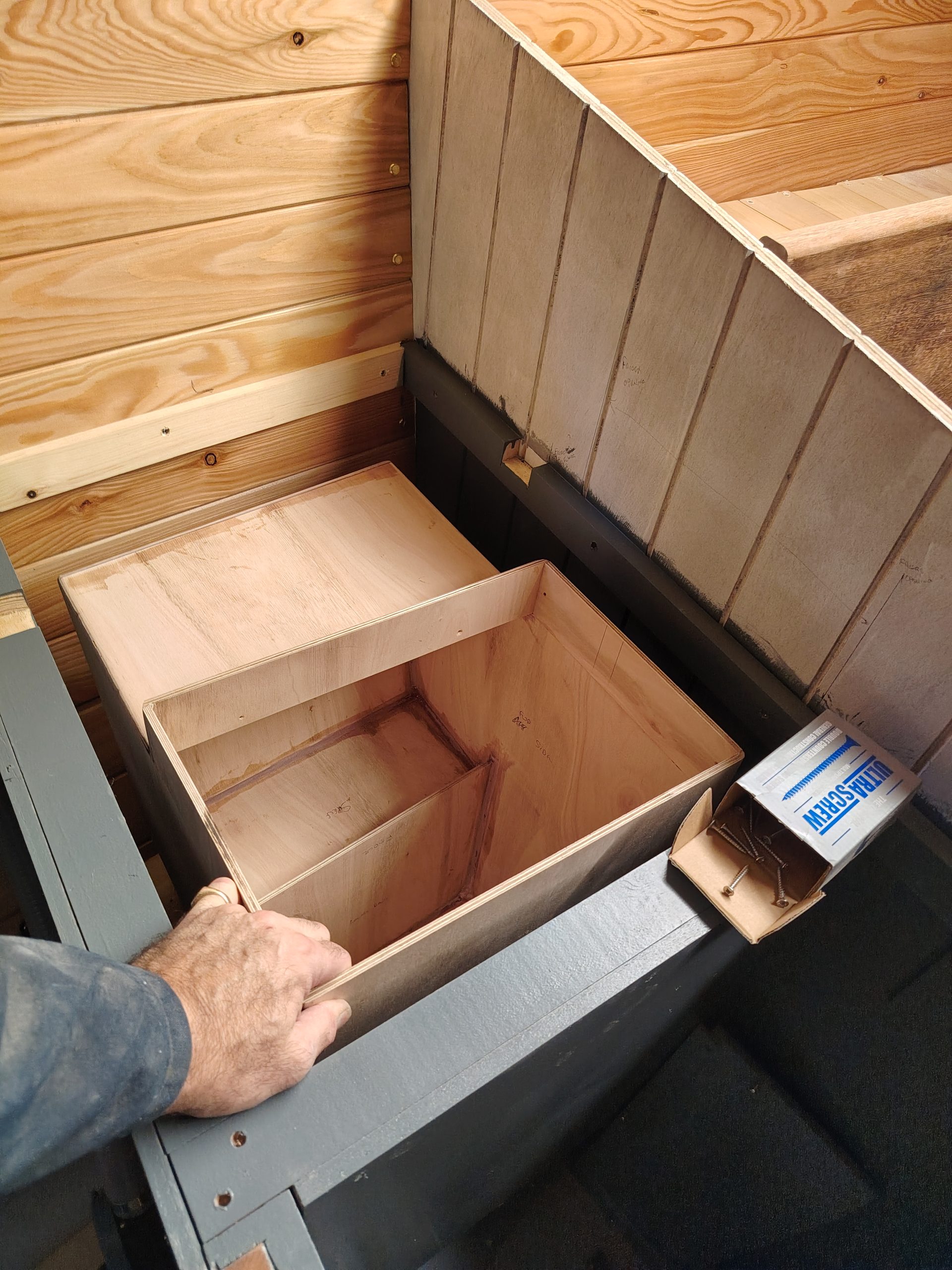
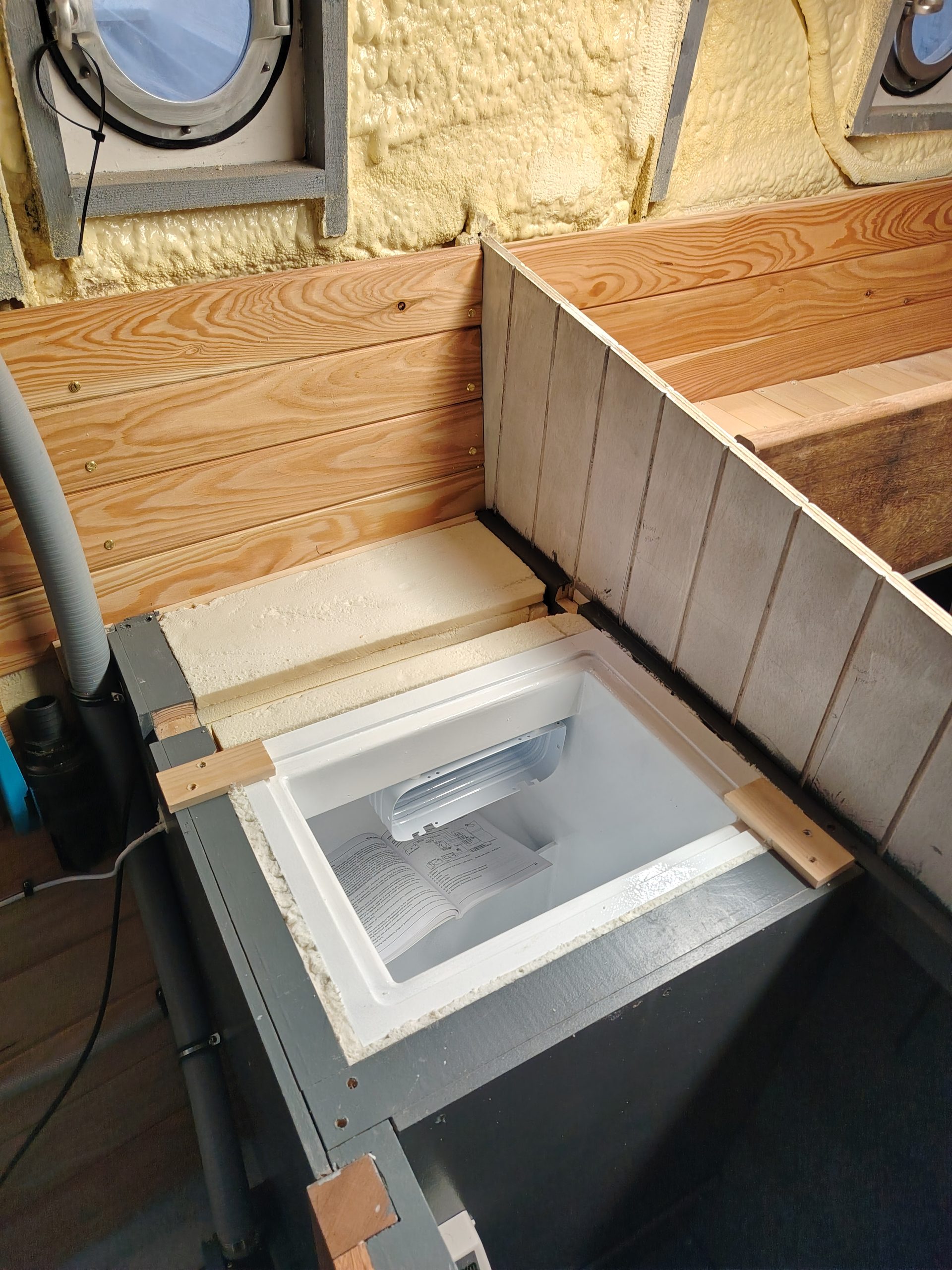
Now came the fun of insulating the locker to fit the box, which was a slightly intricate job, but also messy. Dave, the yard owner, has a pile of unused 25mm sheets of polyurethane foam insulation, so I cut a couple of these up and installed it in layers to line the hole. Typically, my measurements were slightly out, so some planing of sheets to make them thinner was required, and the dust that this stuff creates gets everywhere, and is slightly statically charged, so sticks to you and tools tenaciously! It also uncannily resembles grated parmesan, but I would not recommend putting it on your spaghetti. Once I’d got a snug fit, in went the box, and before committing it to its foamy prison for ever, remembered to cut the hole for the evaporator pipe, and to fit the evaporator plate and thermostat probe. Once these were in place, and the pipe threaded through the side of the cabinet, the box was secured in place by filling any gaps with expanding polyurethane insulation foam, and the drain trap and hose were fitted (with some effort, as short lengths of reinforced sanitation hose don’t bend easily – boiling water was used to soften it), plumbed into the grey water drainage. A trap of course is essential (and will need flushing through regularly) to prevent nasty smells from the grey water tank coming up into the fridge – the same reason traps will also be fitted to the heads basin and galley sink. For some reason it seems that the drains for boat and caravan sinks and basins do not generally come with traps, and also are designed for easily-blockable narrow-bore hoses, rather than the 32mm hoses I am using, with domestic waste fittings and traps.
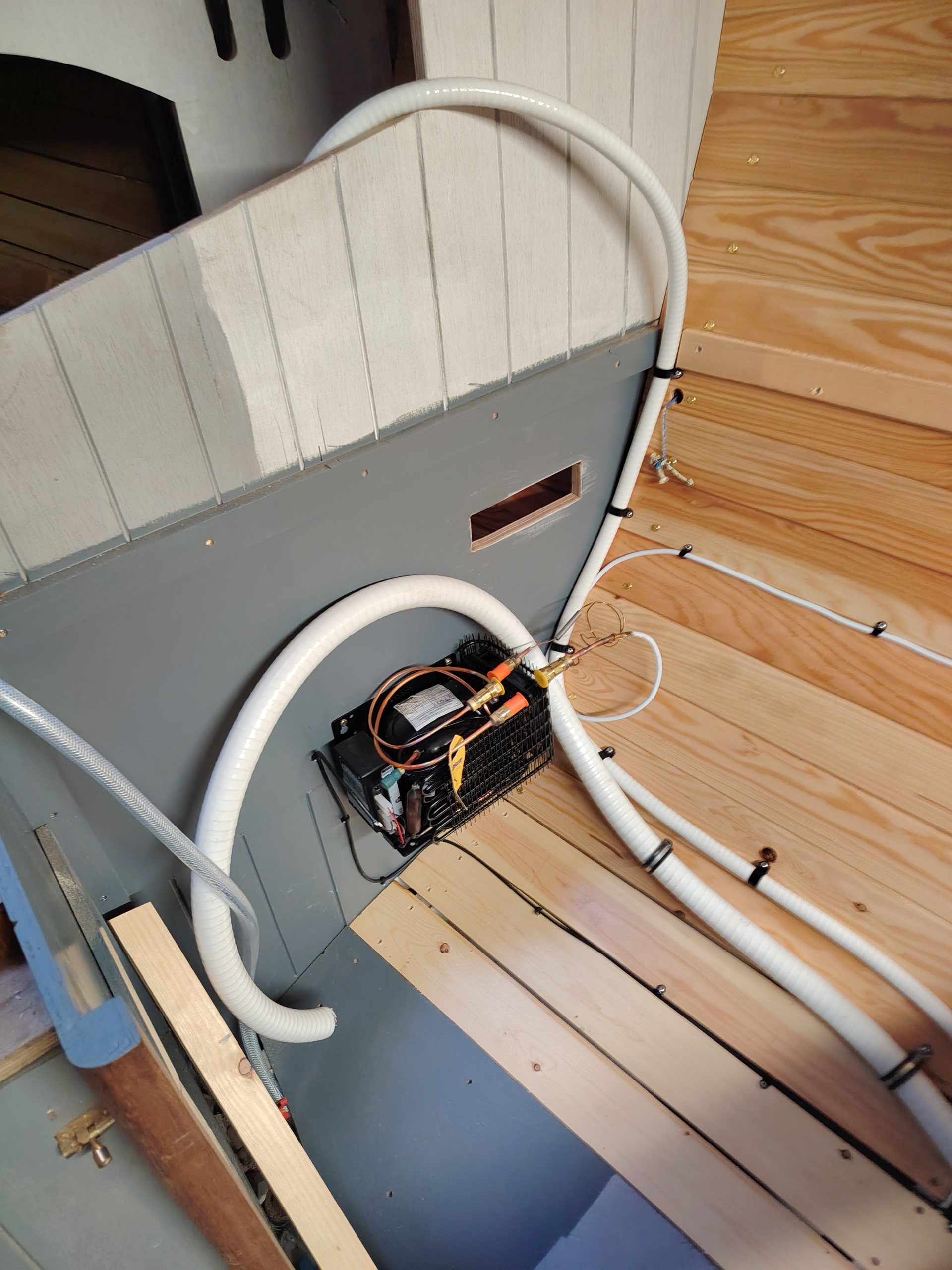
A final couple of jobs I did in the galley before time ran out were fitting the fridge compressor (albeit not yet coupled up with the evaporator, in case I need to move the former whilst building the remaining cabinetry), and the grey water overboard discharge pump, which is under where the cooker will be. I also constructed a lid for the fridge to fit the flange, which was constructed in a similar way to the fridge box, and will be attached to the underside of the hinged lid in the (lab) worktop.
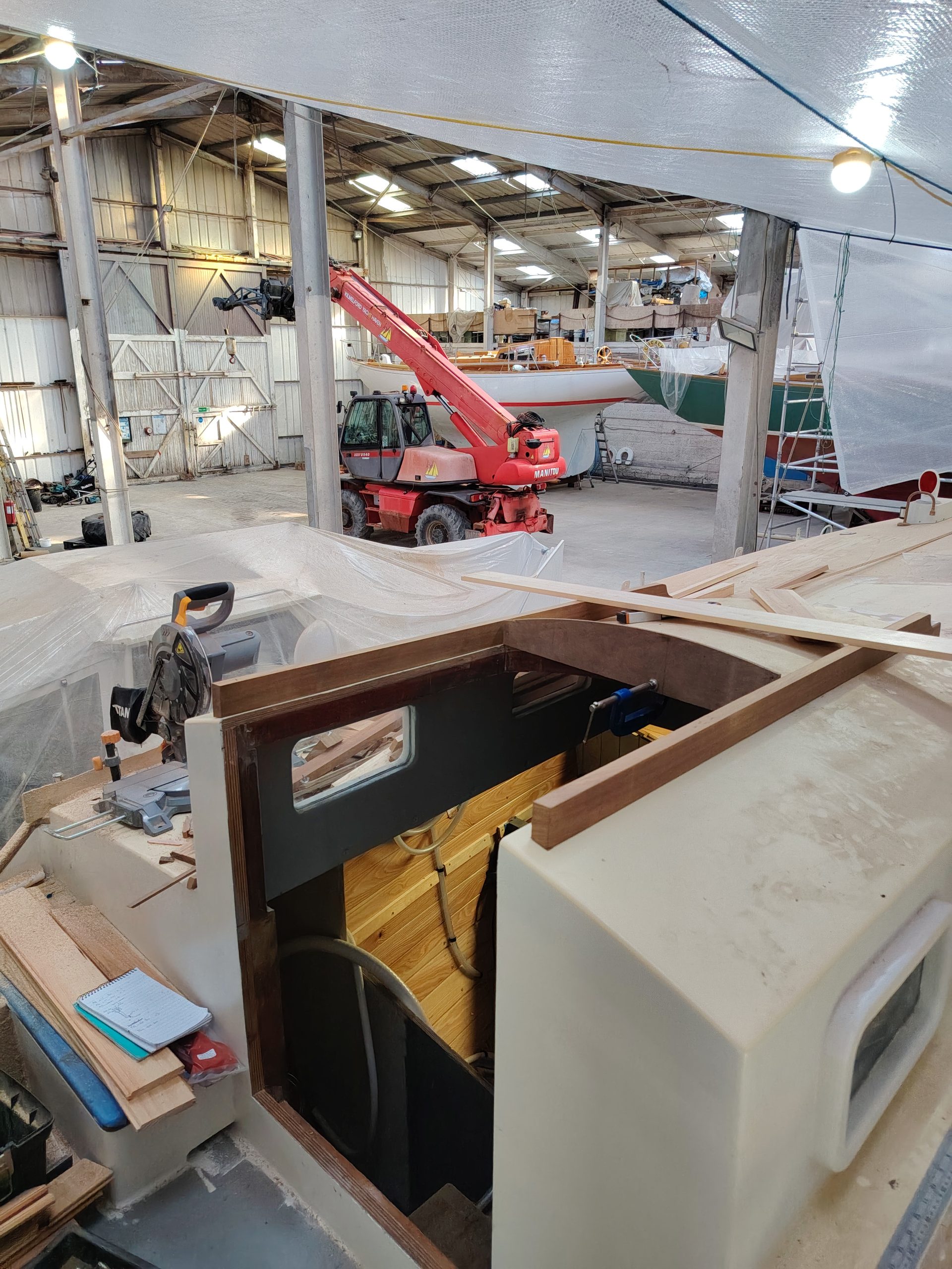
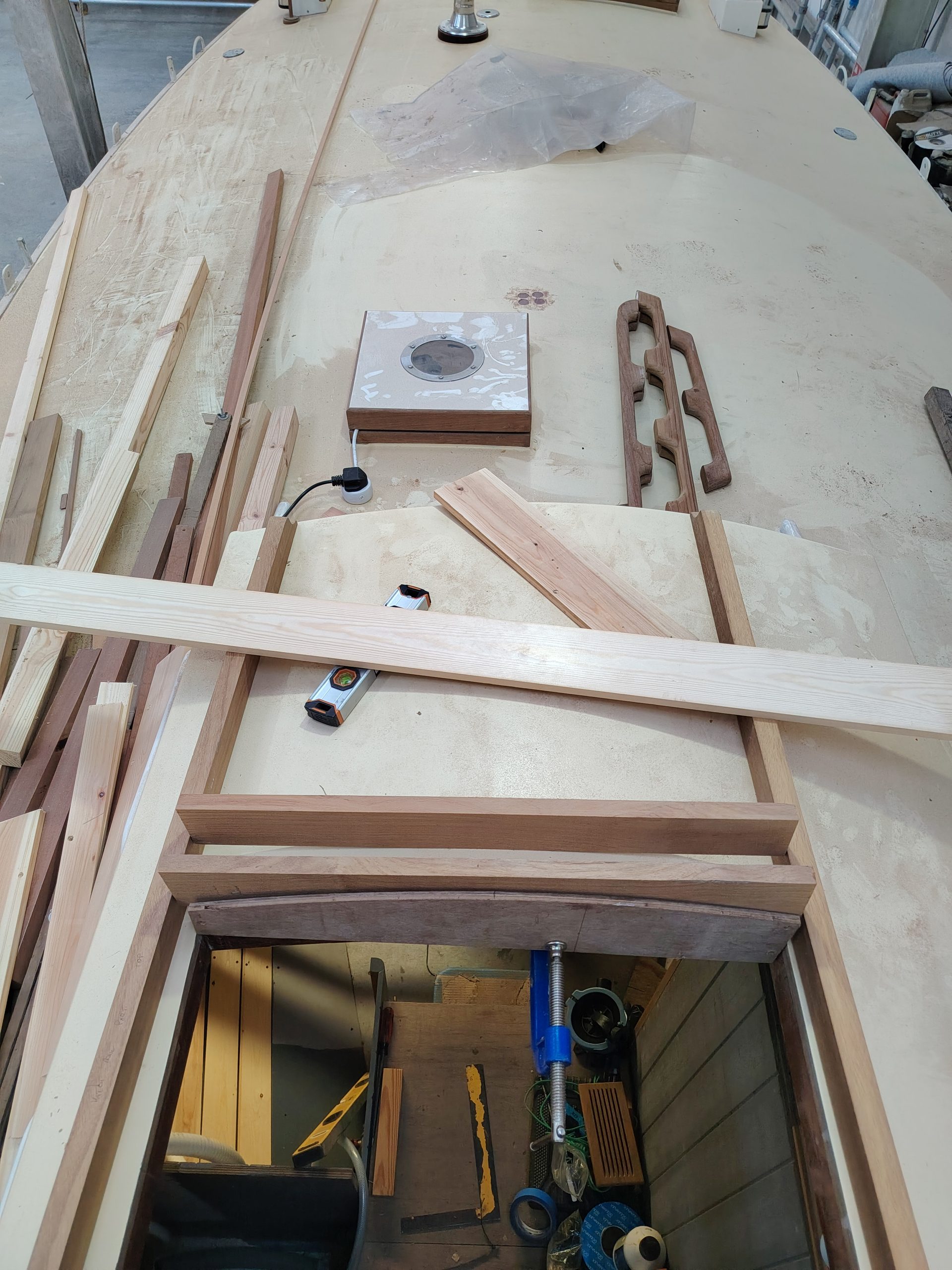
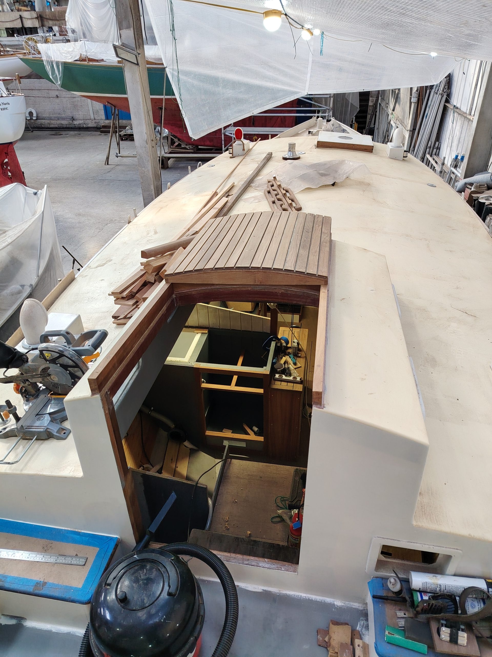
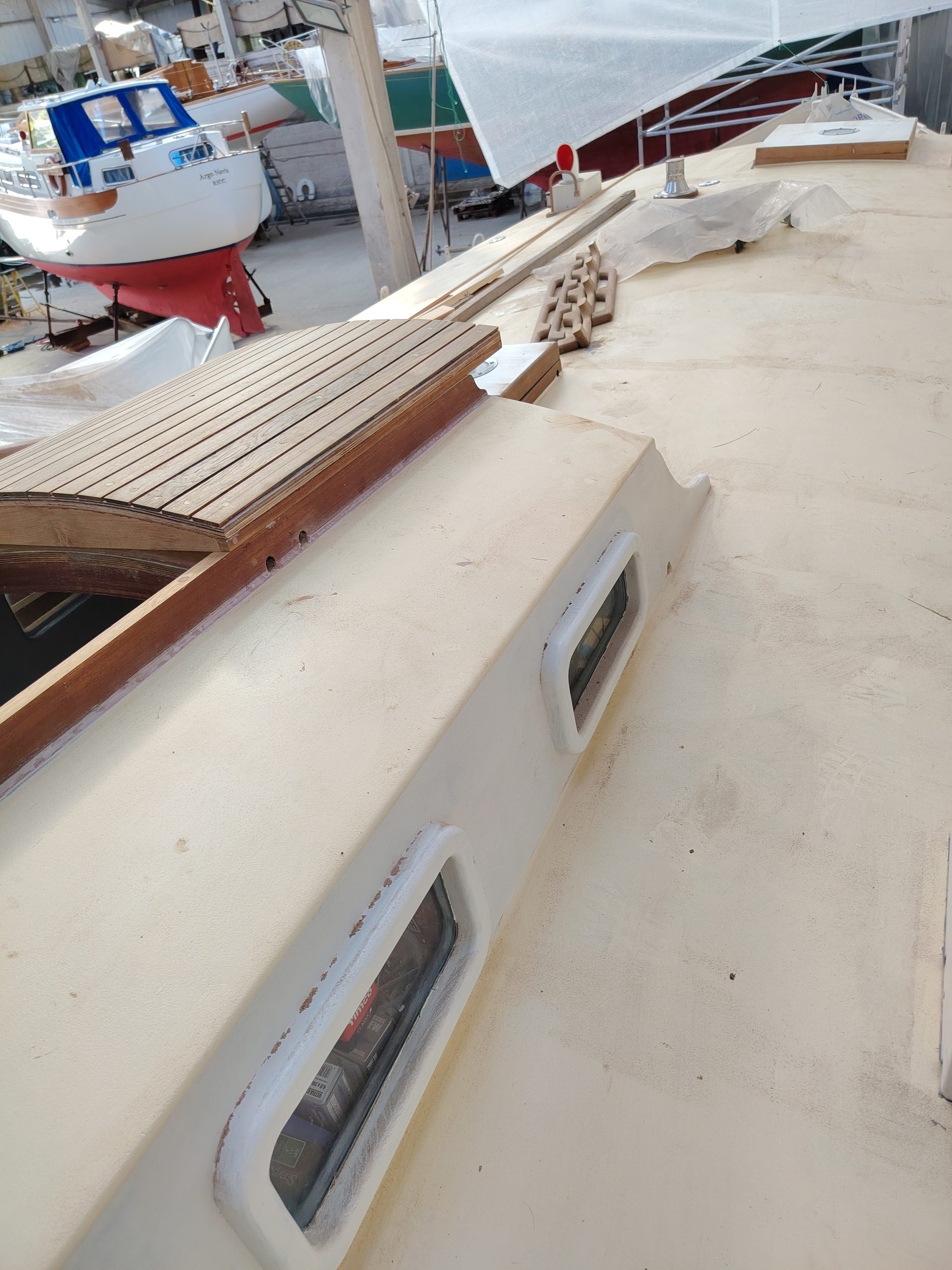
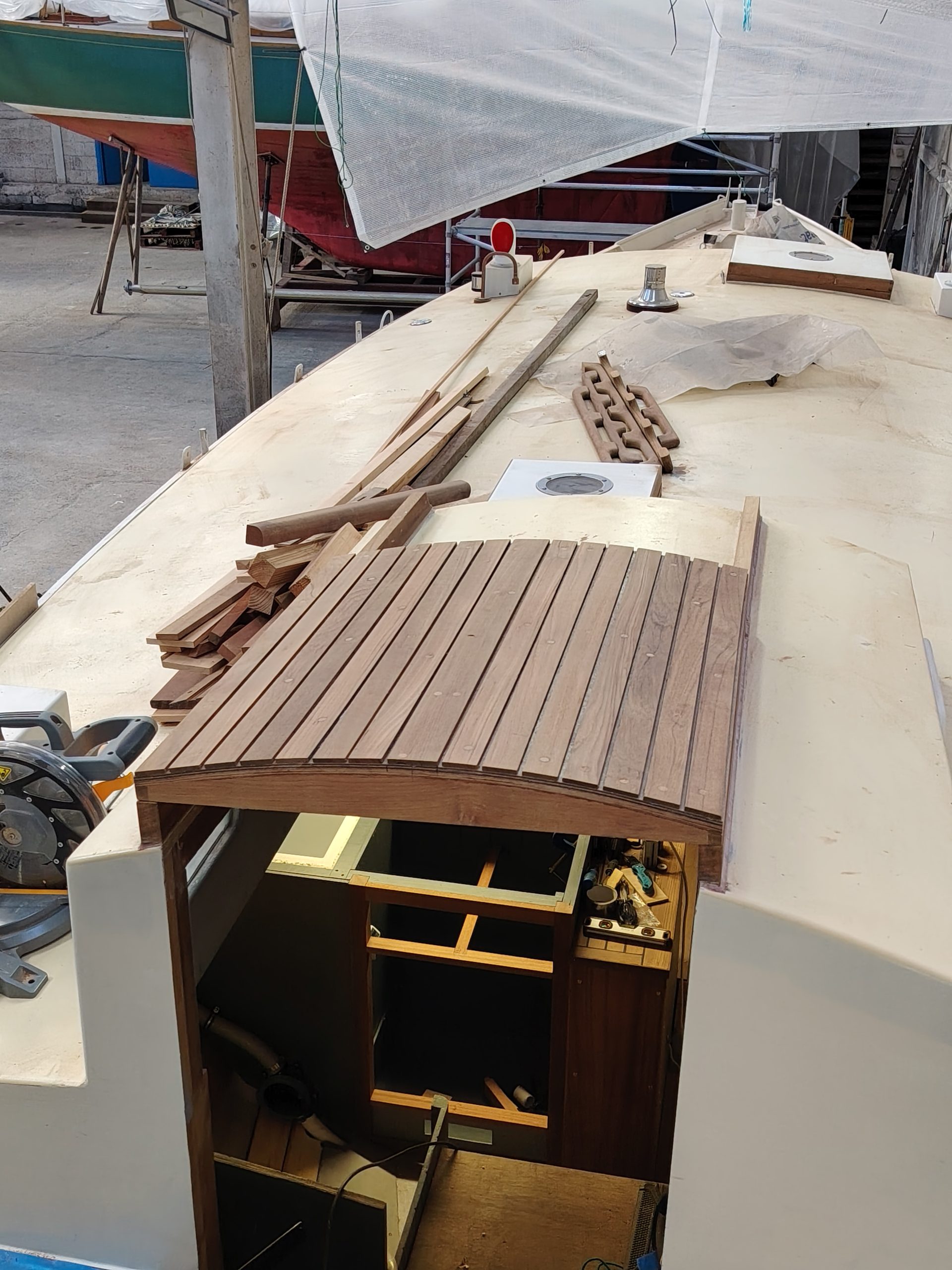
Meanwhile, somewhere along the way, about when I started building the fridge box, I also started constructing my sliding main companionway hatch. This is intended to be as watertight as possible, so I started with the double-coaming design in Fred Bingham’s book Boat Joinery and Cabinetry Simplified. This has side rails with an overlapping brass flat bar slide which fit in slots in the hatch side panels, and two coamings at the forward end of the hatch, the theory being that any water that squeezes past the first coaming drains does not get past the second, and drains harmlessly out of the cofferdam between the two. The sliding surfaces of the hatch cover and rails, as well as the top and bottom section of the coamings, will be brass-lined, and the plan is that when the hatch is slid shut, it can be dogged down so the mating brass surfaces provide a near-watertight seal. It will probably be easier to see in photos than when I describe it, so I will make sure to provide these as work progresses!
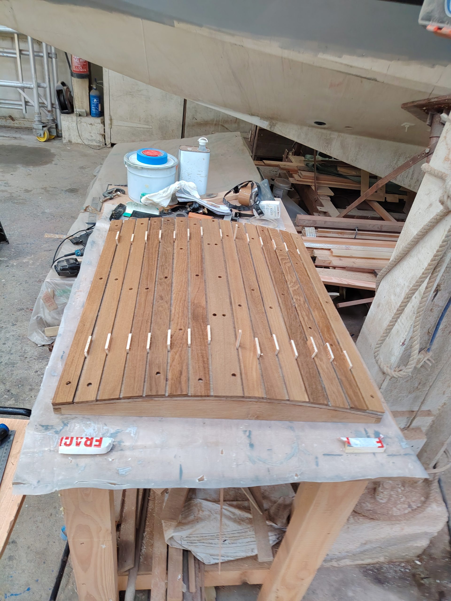
Firstly I selected some timber (all reclaimed to some degree) for the rails and hatch frame. The rails and side frames of the hatch cover are 25mm teak, and the coamings and corresponding parts of the hatch cover frame are 15mm (ish) teak. For the coamings, I cut two boards to the curve of the doghouse roof camber, and used the concave part as the coaming, and the convex part as the hatch frame, to form the same camber in the hatch cover.
I joined the rails and coamings together in situ on the doghouse roof, trying to ensure that the rails ended up parallel, and square to the coamings. It turned out that the hatch aperture itself is not quite square, so any discrepancies will be hidden by trim at a later date. This framework was then epoxy glued to the doghouse, and once cured all joints were filleted. The hatch cover was then glued up on top of this assembly, to ensure an accurate fit. Once the glue had cured, this was taken off and clamped to a flat bench, and an extra ply former temporarily fitted to ensure the camber remains constant in the laminated top, and there were no hollows. It was about at this point that I decided I would add some extra bling to the hatch by finishing the top with more of Trond’s teak, but I initially laminated the top from two layers of 6mm ply and one layer of 4mm (because that’s what I had available). Once cured, this was trimmed around the edges flush with the frame, and a layer of 200gsm glass cloth was applied with epoxy. Onto this I epoxy glued a 5mm layer of Trondteak. After trimming the ends and sanding this top a little, it already looked fantastic. If you look carefully you can discern a slight edge set to a few of the planks as they were originally a swept teak deck, but to the casual observer they would appear straight in the short lengths I used! The next job is to add the side panels which will overlap the rails, whose projecting brass strips will nestle in grooves in these side panels, providing the sliding “mechanism”. Panels or trim will also be added on the forward and aft faces of the hatch and will also act as stops for the hatches forward and aft movement, and further prevent water ingress. The aft panel will incorporate a lip to which the near-watertight folding hatch boards will seal.
I think this pretty much sums up the progress in the last leave, and I am looking forward to the next one and to the continuation of these projects. In the meantime, there may also be more developments on the job front, as my quest for a job that doesn’t want to break me mentally and / or physically continues. Watch this space…










Nice one Chris. I admire how you are able to write this up in so much detail. I’m hoping I live long enough to see her afloat.
Good luck with the job hunt.
Thanks Colin! I’m hoping she may get in the water in 2028, fingers crossed!