Unexpectedly Long Leave = Lots of Progress
I last updated you in late July (or was it early August? A while ago, anyway), and had done lots of little bits, fitted the centreboard, painted the hull and made progress with the preps of the interior for the installation of the foam insulation. I was expecting my next leave period to be a similar length as the previous couple – a couple of weeks, during which I had booked in a 5-day trip as “Trainee Skipper” on board the steam puffer VIC-32 – so I was expecting and hoping to complete the preps for the insulation in order that the foam could be sprayed in before the winter (and therefore condensation) really set in.
First of all, a little bit about the puffer. There are few modern seafarers who could say that going for a run on a steam-powered vessel could be a step up in propulsion technology, but I guess I can probably make that claim! VIC-32 is a former Admiralty victualling tender, of which a whole flotilla was built on the lines of the classic Clyde Puffer (think Para Handy and his Vital Spark). These are small, simply built steam freighters, which at one time swarmed up and down the West Coast shifting cargoes between islands and mainland, and which were ideally suited to the job: cheap to run and man, small enough at 20m length to go through the Crinan canal, and flat bottomed, so they could be beached for loading / unloading if suitable harbour facilities were not available. VIC-32 is one of only a handful of survivors from this fleet, and of even fewer still operating, and yes, she did play the part of the Vital Spark in the BBC Para Handy series made in the 90s. For many years she has been in the hands of the Puffer Preservation Trust and has been based in Crinan, taking paying passengers out for cruises and day trips up and down the West Coast. It was suggested by some other ex-JST folk that I might enjoy playing on board her, so I got in touch with the Trust and booked myself in for a trip to give it a try.
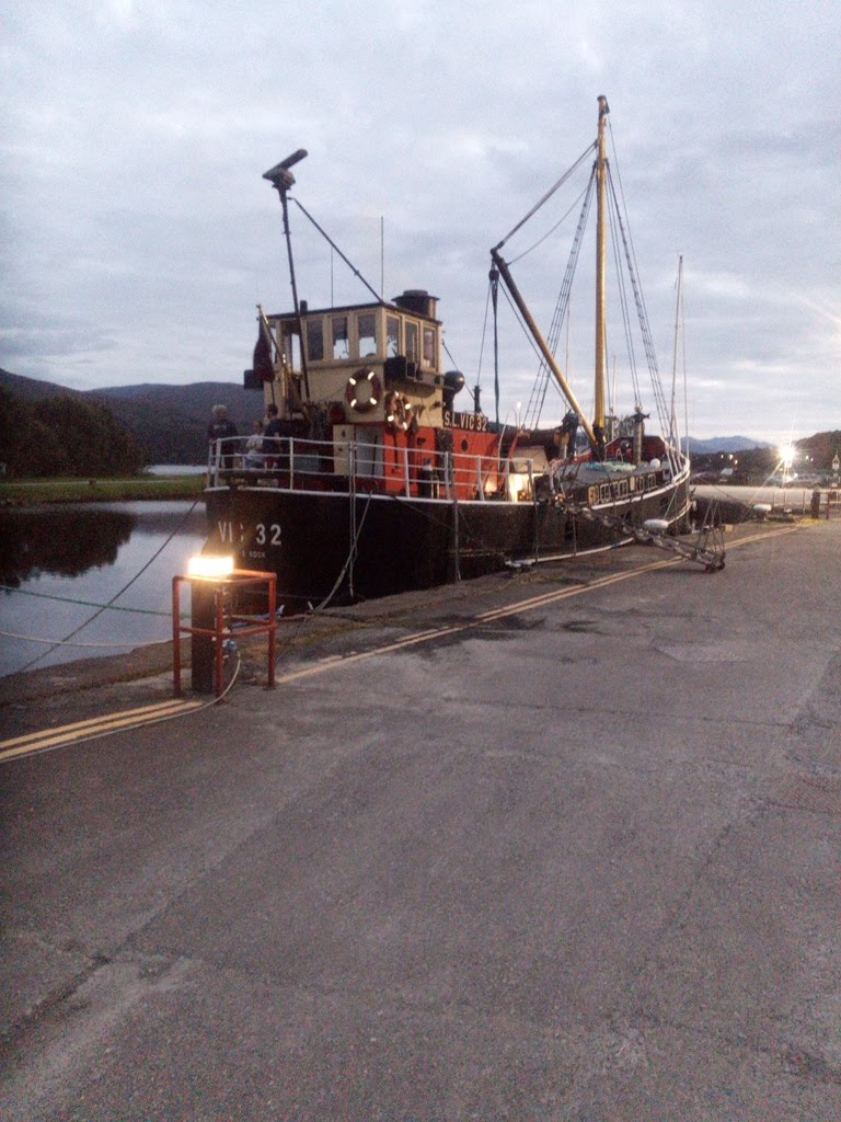

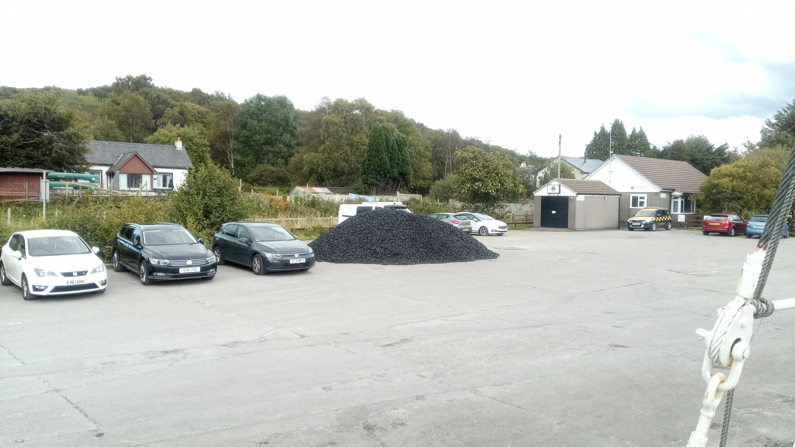
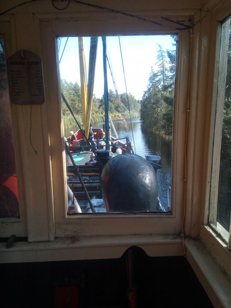
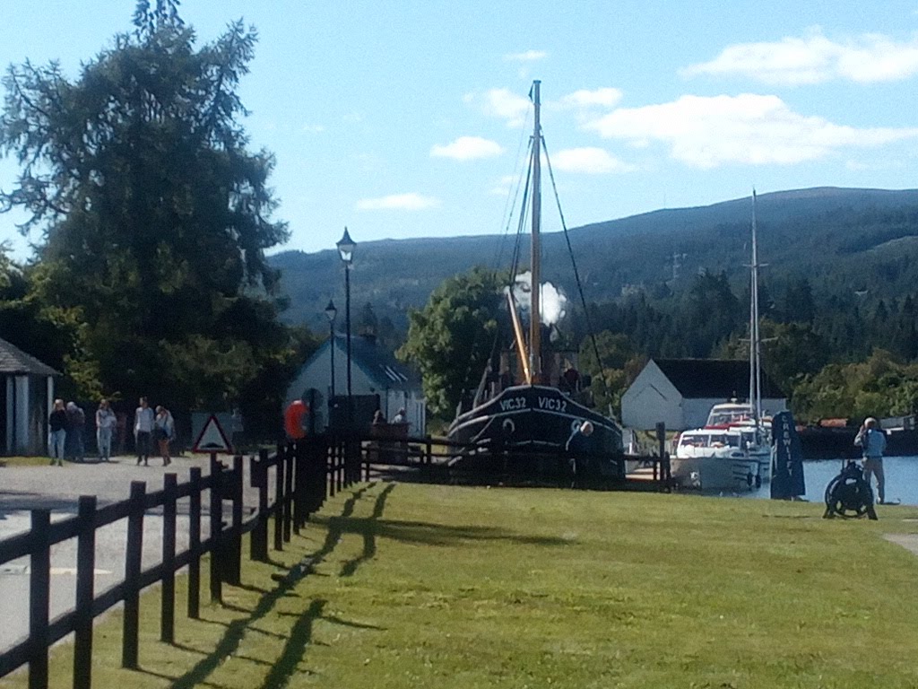
The trip was a northbound run up the Caledonian Canal, so I drove up the coast to Fort William and joined her in Corpach basin. After a short familiarisation the passengers joined, and our first job the following morning was to coal ship, manually loading (by passenger power, shovel and wheelbarrow) 6 tonnes from the large pile of Ovoids on the quayside (the Trust has spent this season experimenting with various types of smokeless fuel, as it is almost impossible to get hold of “proper” coal these days). Then we were off up the first locks and into Neptune’s Staircase. Our progress up the canal was leisurely, but we were blessed with some fantastic weather and a pleasant bunch of folk on board. From knowing nothing about handling a steam-driven vessel at the start, by the time we reached Inverness I was a dab hand at manoeuvring her, particularly in and out of locks!
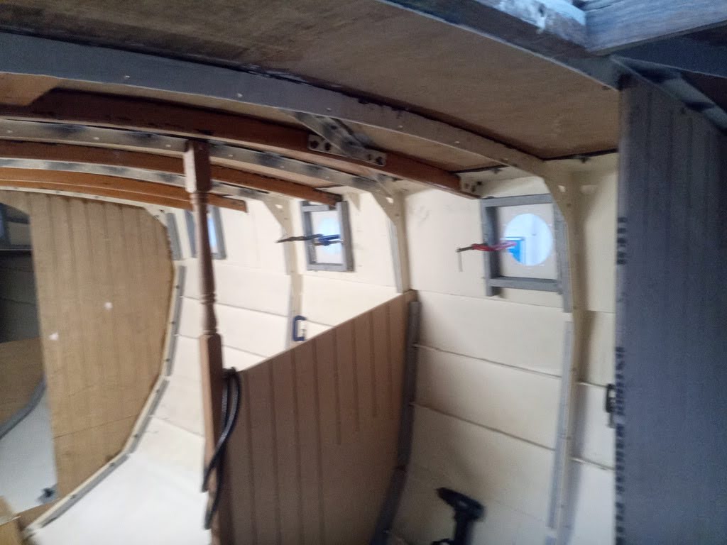
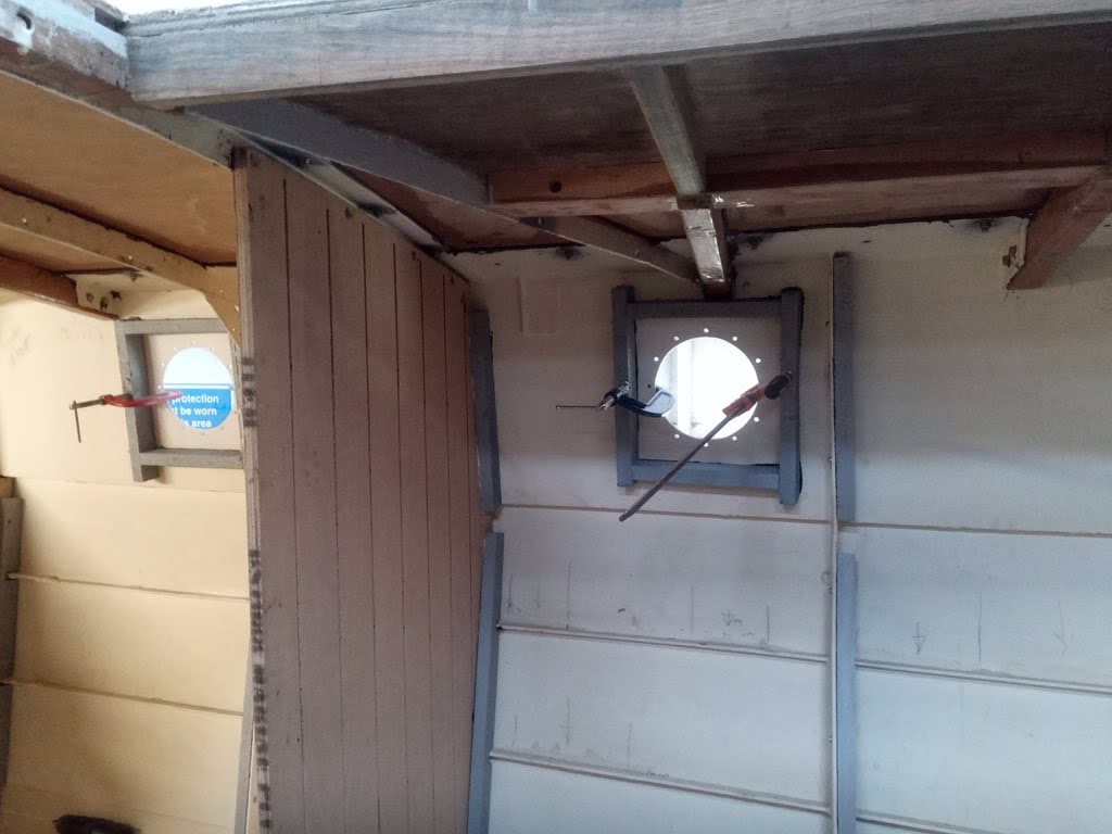
Anyway, either side of that little jaunt I continued with my work on Serchthrift, finishing the preps for insulating. This consisted of constructing and fitting the boxes around the portholes, finishing the cable conduits on the starboard side and finally fitting a pair of teak blocks to the aft end of the cabin sides for seating the cockpit bulwarks. The main reason for doing this at this stage was that there were three holes drilled in the steel for through-bolting something, and it seemed logical that the cockpit bulwarks needed attaching somehow, so I devised a plan and made the blocks out of some teak which I had in my stack which were then bolted and glued to the steel with copious quantities of black poo.
The porthole boxes had to be individually designed and constructed as each one interacts differently with nearby deck beams and frames. The basis was always the same, and fortunately I could at least make them in pairs, as port and starboard sides were, on the whole, identical! Where I could I used screws / mechanical fixings to other parts of the structure, but where necessary, as they are not structural, I used the ubiquitous black poo to stick them to the steel plating of the cabin sides (after much wrangling with spirit-level to ensure they were square).
The conduit went in fairly easily, and on the stbd side I fitted it in one continuous length, looped around the frames and to be trimmed back later, unlike the port side which I cut at each frame and struggled to keep the ends accessible when the foam goes in.
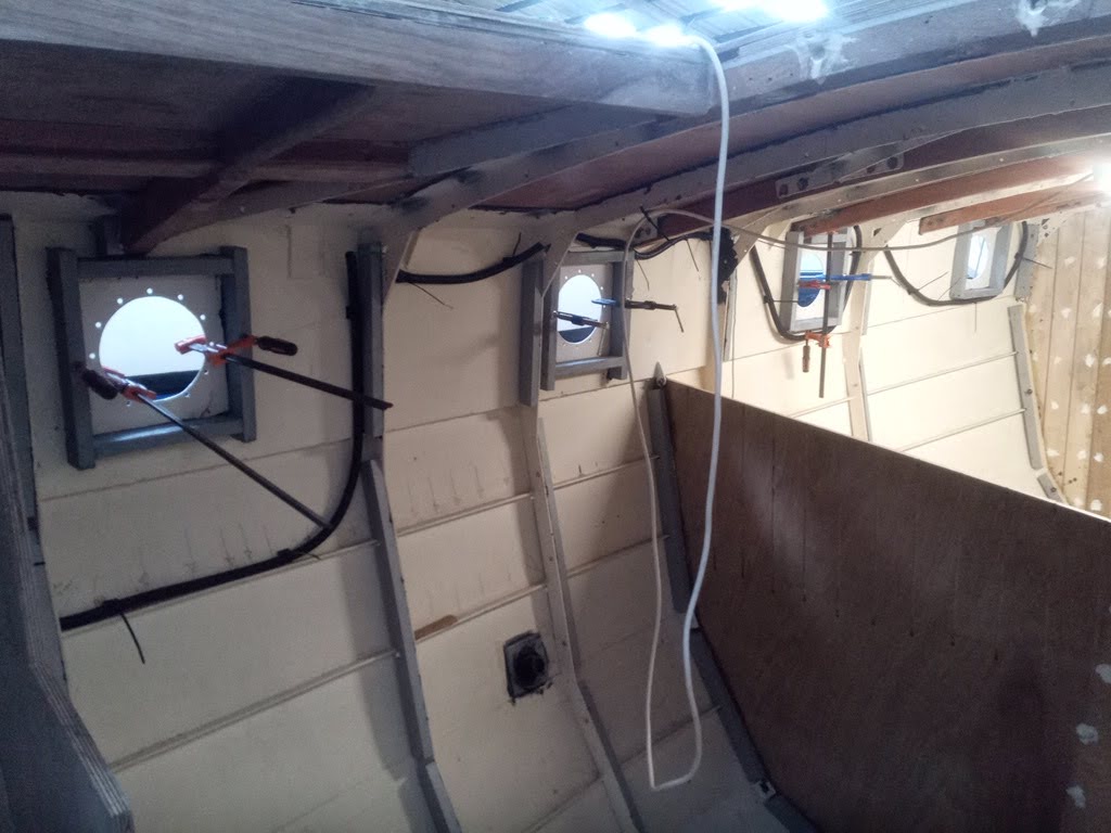
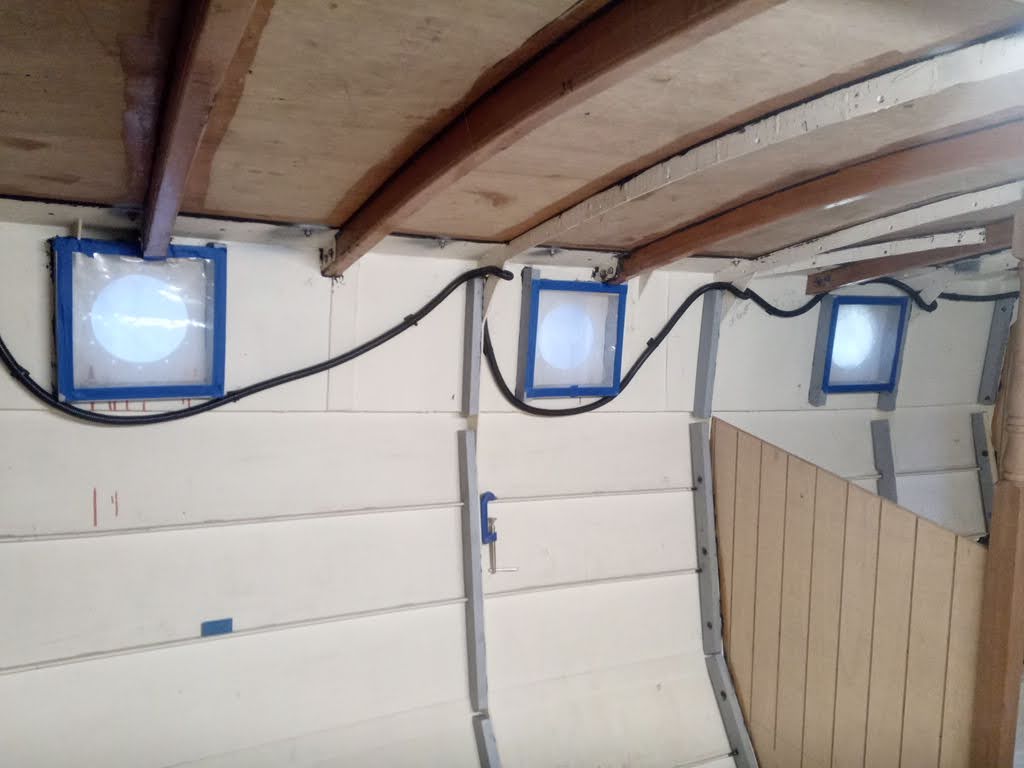

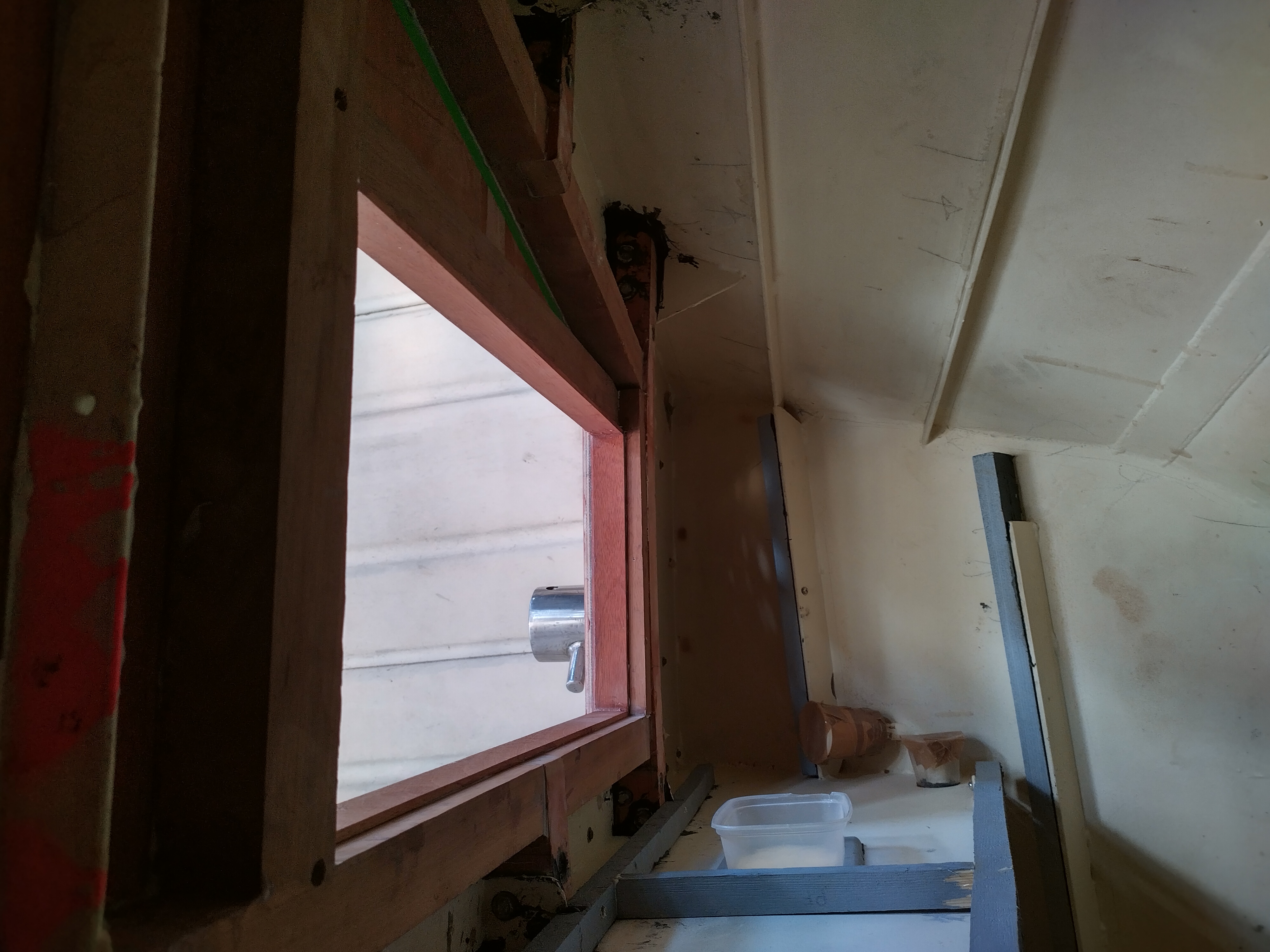
The final job to complete prior to foaming was ensuring the through-hulls were adequately encapsulated / masked off so that when the foam is applied, they have a recess around them allowing access for hoses and tools. This I achieved with a mixture of plastic containers, parcel tape, paper cups and a cereal box! Once this was done, I could confidently contact the foam sprayers to tell them I was ready and to fix a date. The company I used was the only one I contacted which was able to give me a quote, but it was reasonable, given the scope of the job, and despite the time elapsed between getting the original quote and being ready to proceed (which was just over a year), they did not feel the need to change the quote due to fuel costs or cost of living, which made me happy. In compensation for that, they turned out not to be very good at communicating, but you can’t have everything!
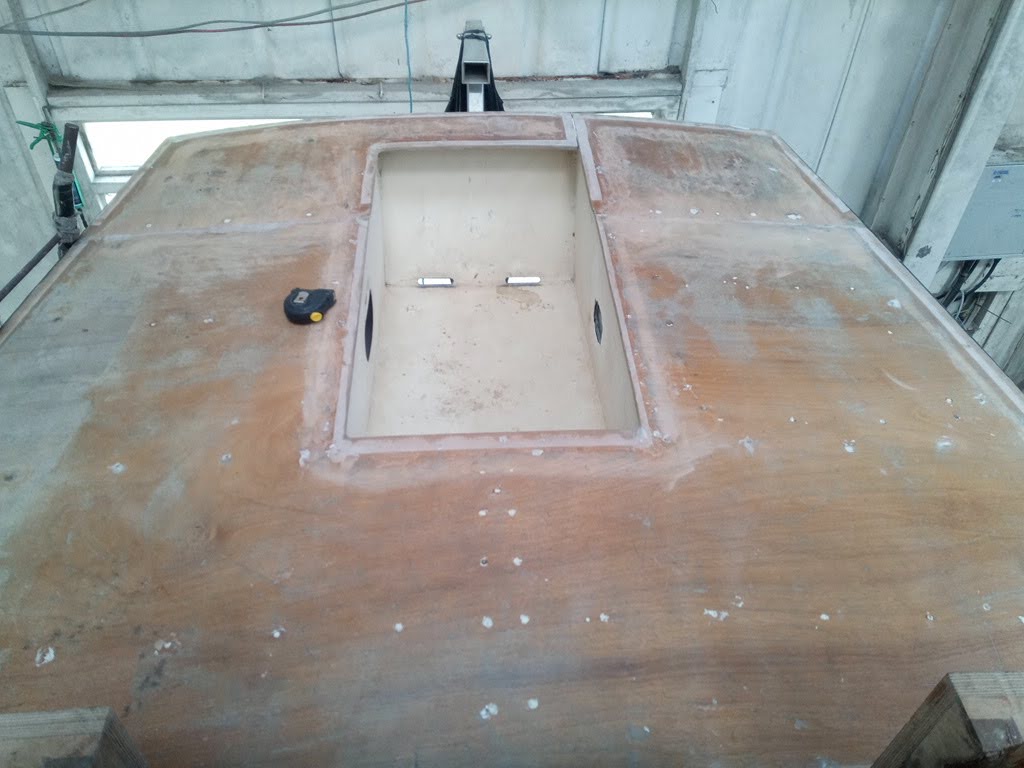
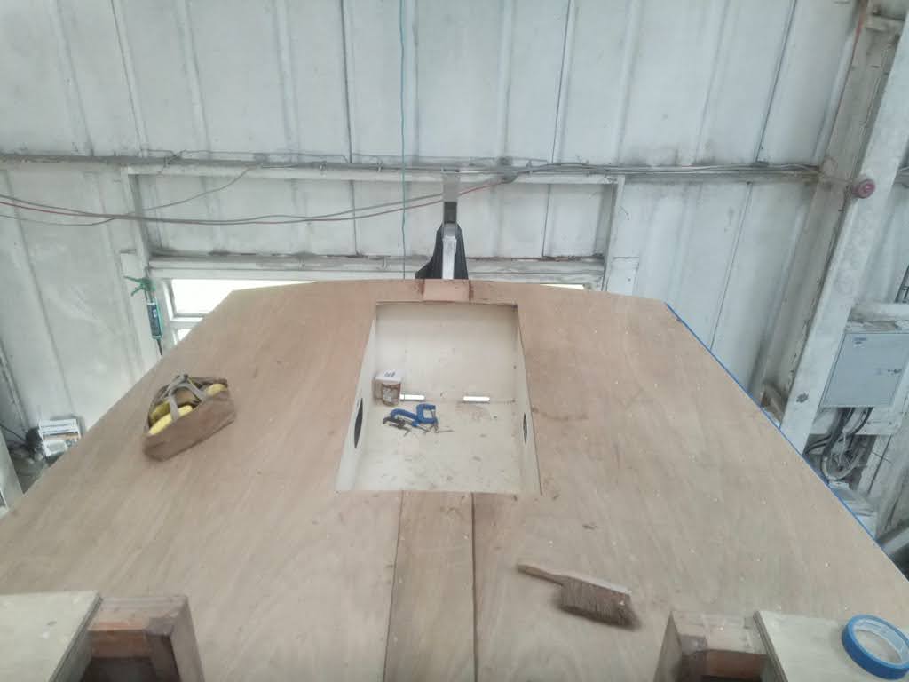
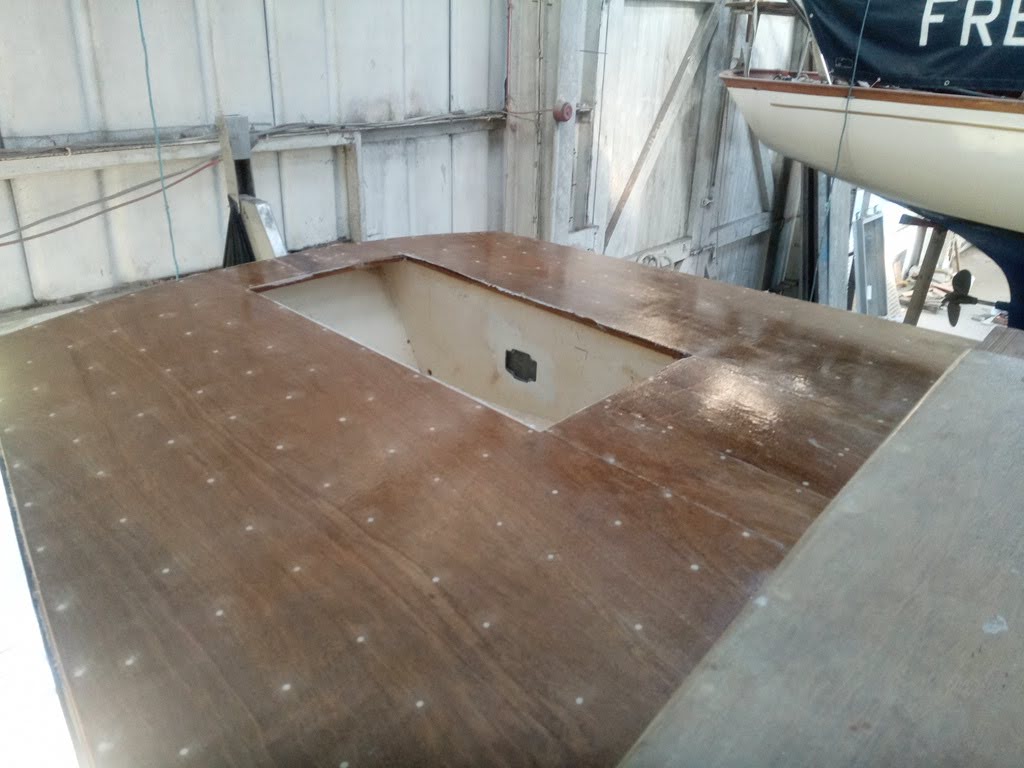
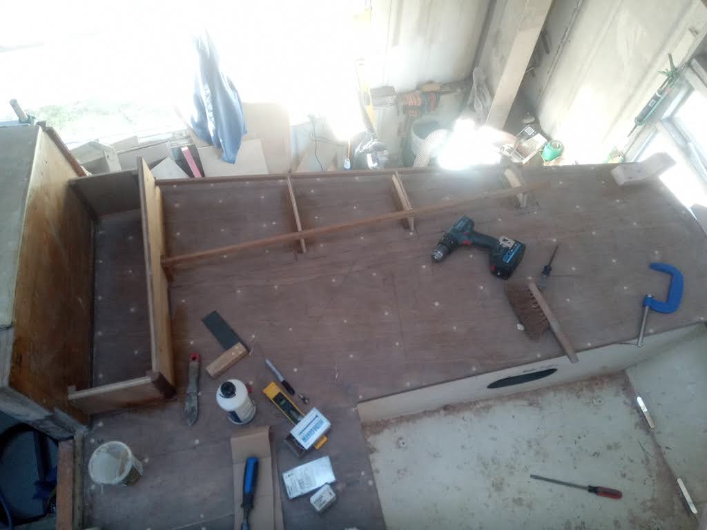
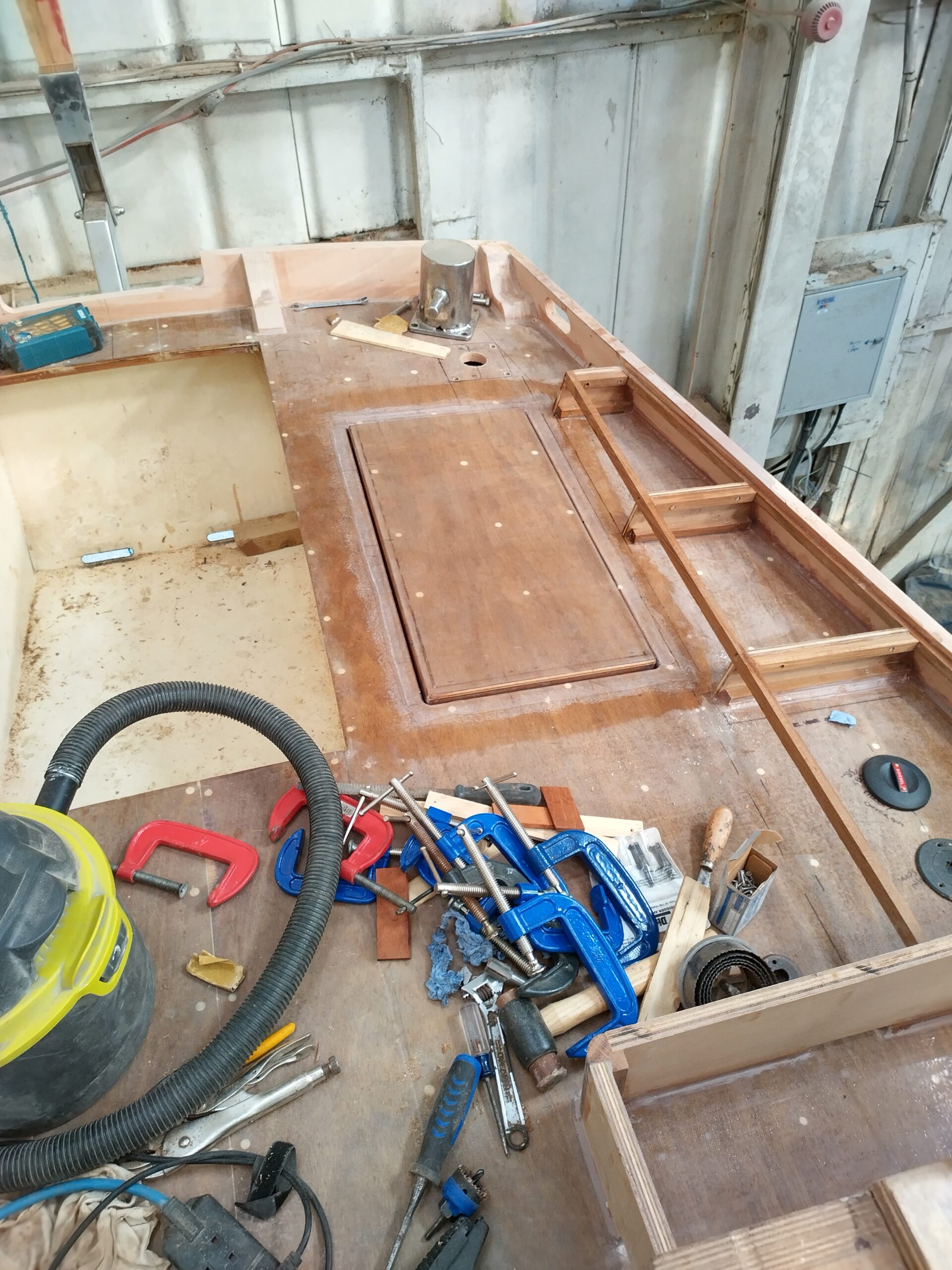
Having got the interior ready, and clean, for foaming, I then had to start on an exterior job, so I decided it was time to tackle the cockpit. Now, for some reason, when Guy originally built the hull, he did not fit steel bulwarks to the cockpit to match the ones on the foredeck, as per Nick’s original design. I do know of other Wylos which have not had these fitted, but cannot think of a good reason for doing this, either from the point of view of aesthetics or for protection of the cockpit / aft deck (not all Wylos have an actual cockpit well, just a sprawling area of flush deck with a hatch to the locker beneath). Anyway, I had long ago decided that I would replicate what should be there using marine ply. The first job however was to lay the second layer of ply on the existing cockpit deck, as I had on the main deck previously (back in late 2020 as I recall…). As I had up until this point been using the aft deck as a repository for tools and a general dumping ground, the first job was to tidy up, then I had to ensure that the whole surface was fair, clean and sanded. I still had some 9mm ply left from when I did the deck (as I had accounted for the cockpit in my ordering), so next I took two sheets and marked off the shape. Unfortunately, the widest part of the cockpit deck is about 20cm more than the width of two sheets of ply, so there was an annoying gap in the middle to fill in, but this was not a real problem. Once cut and shaped, I glued the panels down with thickened epoxy and secured them with oodles of screws, as I had with the main deck. After this had cured, the whole deck again was faired and filled, and faired and filled again, with the edges being rounded and sanded around the gunwales, and trimmed around the cockpit well in readiness for eventual edging with hardwood trim, before sheathing with a layer of glass cloth and three coats of raw resin.
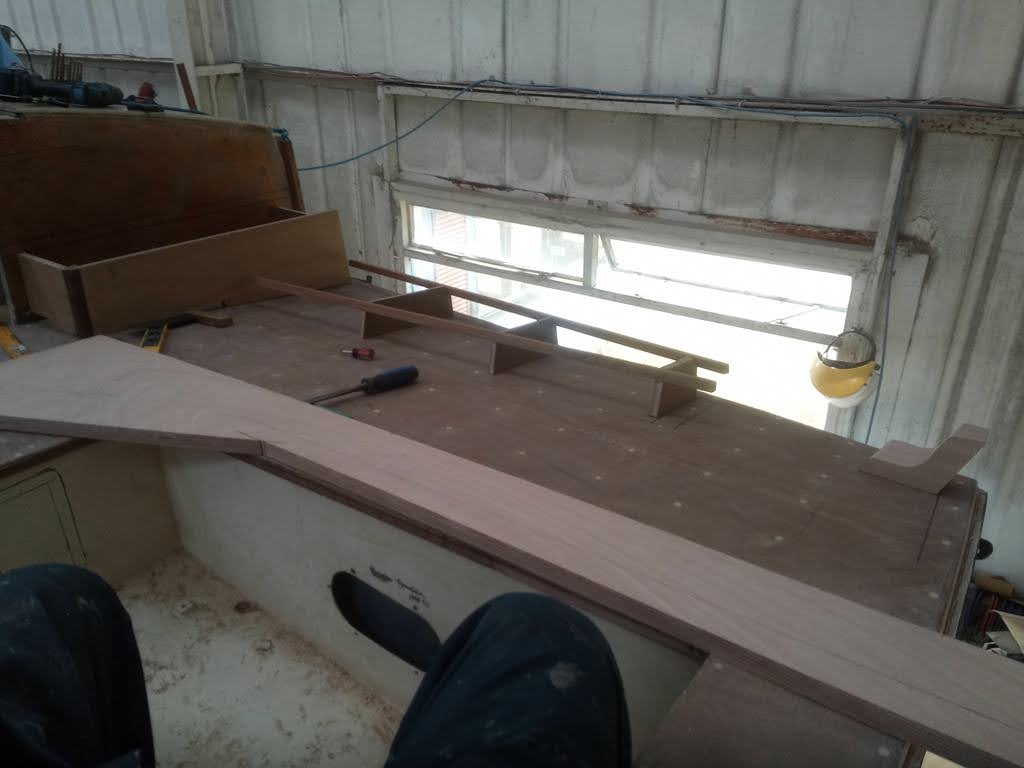
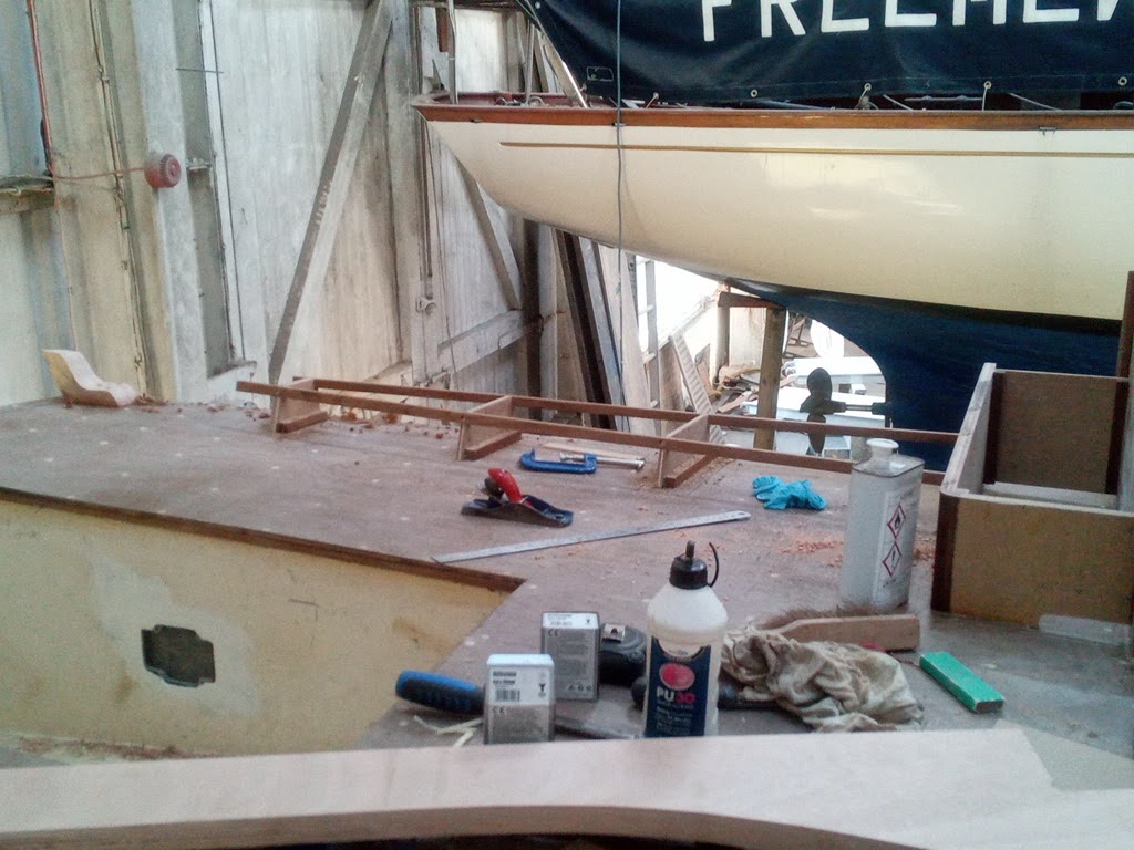
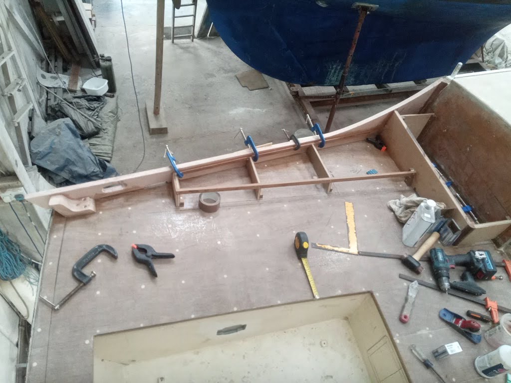
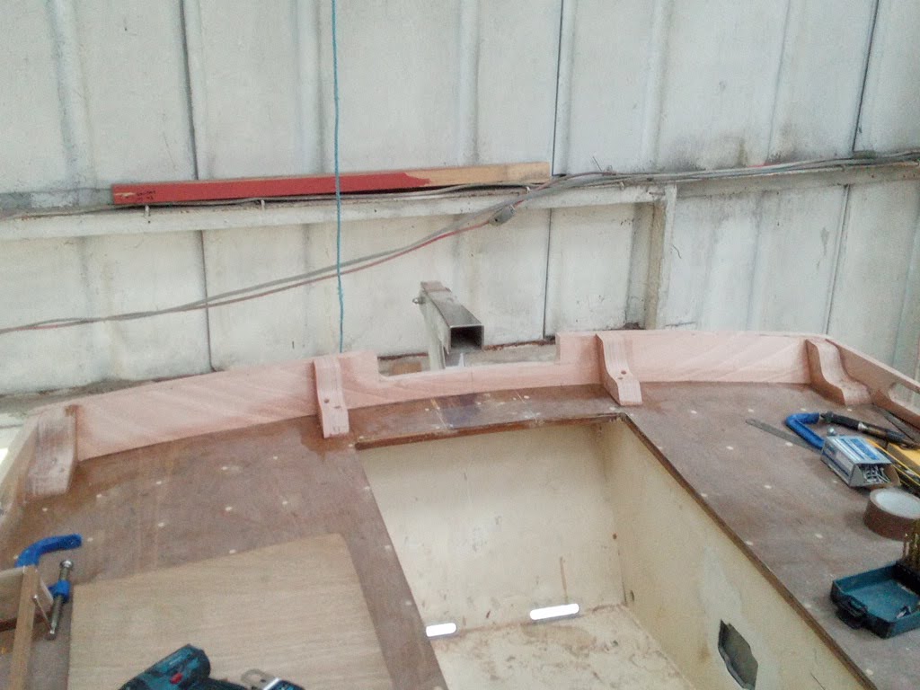
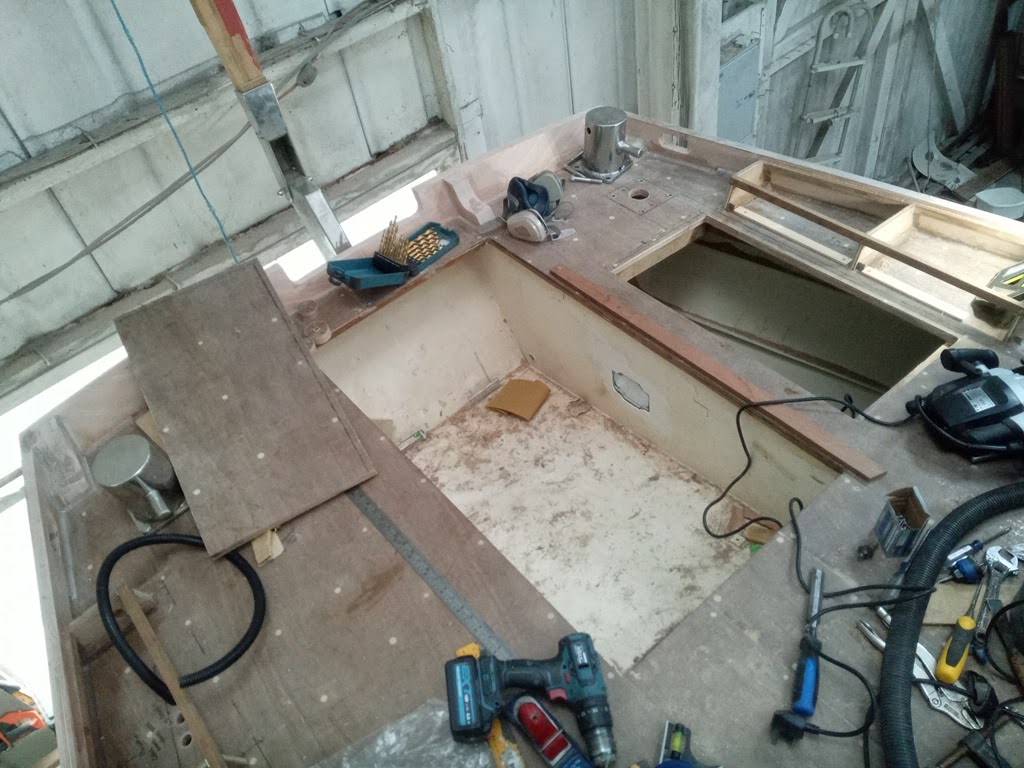
Next, I had already decided on the rough layout for the cockpit, and had made some provisional drawings, but needed to double-check measurements before starting construction of the bulwarks and “furniture”. The most tricky bit to get right was the relative positions of the port seat back and the aperture for the cockpit locker hatch – the latter being pre-determined by the framework underneath, which had been constructed by Guy. With decisions made, I started constructing a framework and some rope lockers either side using scrap bits of ply and some teak strip. The rope boxes will form a useful step from cockpit up to the main deck, and also provide a bin either side for the tails of halyards etc., which tend to be long with junk rig! Extending aft either side from the rope boxes are then some areas of slightly raised side deck in between the bulwark and the seat backs. The main purpose of these is to provide a solid support for the shallow backrests for the cockpit seats, but also they fill in what would otherwise be a bit of an awkward gap / well between the bulwarks and the side decks. This construction also allows me to incorporate a sealed watertight fuelling locker, to avoid the embarrassment of spilling fuel over the side of you have an overflow when bunkering. This will be accessed from above by a proprietary watertight deck access hatch (also lockable), and will contain fillers for both the main keel fuel tank, and the day tank which will be under the cockpit sole. I decided however not to use the remaining sections under these raised side decks for stowage, as they are all quite shallow and their utility would be limited.
I also chose to incorporate a recessed step at the forward end of the bulwarks, allowing easier boarding over the bulwarks from a dinghy or pontoon. This meant building a separator board at the outboard end of the rope boxes to keep feet and ropes separate. All of this framework was quite fiddly and complicated and took a while to produce and fit, but was worth doing well.
It must have been at about this point that I got the phone call from work saying that the refit of Fridtjof Nansen had been paused to regroup following the result of the thickness measurements of the hull, and the decision that quite a lot of steel needed replacing. As a result, all volunteers and crew who had been standing by and helping on the refit were being stood down, and although I was due to return that week, I should stay at home and await further instructions. From the point of view of working on Serchthrift, this was good news, as it meant I could carry on and make progress, but it was unsettling nonetheless. Whilst work made up their minds what I would be doing over the winter, I contacted the insulation company and fixed a date for early October.
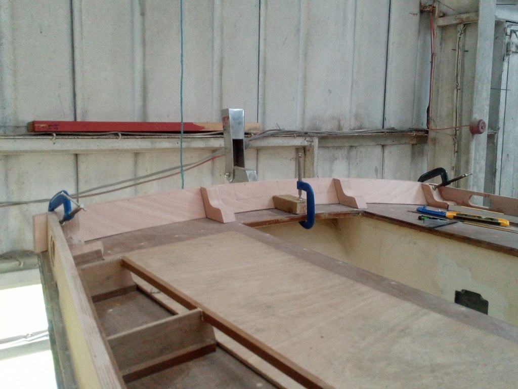
At the same time I templated and cut the first bulwark. I worked out the radius of the sweeping curve down from the main deck from the drawings I had made previously (based on Nick’s original plans), and this swept down to the sheerline 100mm above the cockpit deck all the way to the stern. I cut it overlength and left the curve rough cut until I was happy with the profile of the bottom edge, then cut the curve on my new bandsaw. The lines were all cut at a 10 degree (ish) bevel to match the camber of the deck combined with the inward slope of the cabin sides, and cutting a compound curve like this on a board over 6ft long was quite fun!
Before finally fitting the board, I had to fabricate a knee to secure the aft end to, and to support the bulwark across the stern. I laminated three pieces of 25mm ply to form a block, and planed the edges smooth and to the correct angles, before cutting the curve on the bandsaw. Before I fitted it to the deck I took the profile off as a pattern for the other three knees I would need to support the full width and the other side bulwark. I also took the pattern of the bulwark board to use to cut the one for the port side.
I was finally ready to fit the first board, and with copious amounts of epoxy, some fastenings and many clamps, I did just that. Because there was a slight twist in the board, it was quite tricky to clamp the forward end, but a combination of hope, clamping and screws did the trick. I then cut and fitted the second one.
Once both sides were fitted, I had to make a template for the transom bulwark. Whilst the transom itself is flat, because it is both at an angle and has a cambered top, the board had to be cut with a fairly considerable curve to it, so I used a straight plank as a spiling board to take off the curve to match. Having shaped and fitted the knees and made a cutout for the tiller, I fitted this last board and faired off the ends and tops as necessary.
Now the bulwarks were all in place, glued and screwed, they then had to be filleted with filled epoxy at the joint between the bulwark and the deck. The easiest way of distributing the filler along the join was using a bag to “pipe” it like icing. This means that one can spread out the epoxy quickly before it starts going off, which I have found is the hardest part of working with epoxy. If it is left in bulk in a mixing pot it goes off surprisingly quickly, which produces a lot of heat, some smoke and fumes, and can catch fire if there’s enough of it. The best way of preventing this is spreading it out as quickly as possible, at which point it stays workable for much longer.

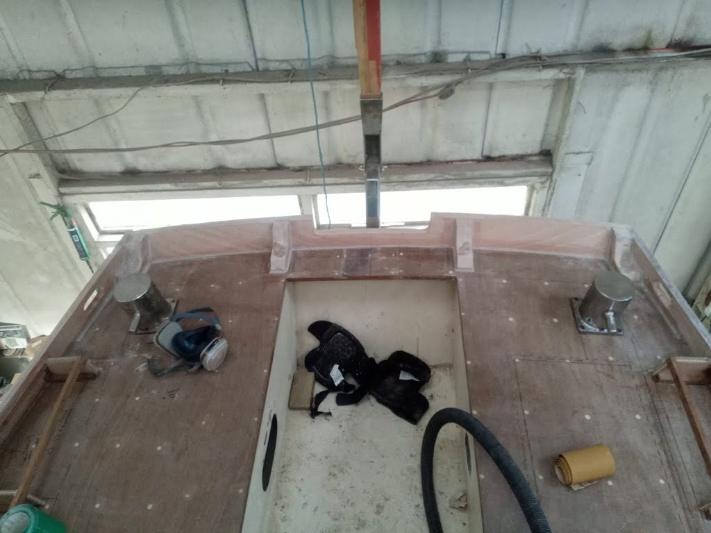
Whilst all his was going on, I was also marking and cutting holes for the fuel fillers, cable conduits for the sternlight and other electrical cables to the pushpit, as well as for the autohelm (I also marked the position for the autohelm pivot socket). Finally I had to determine the final position of the mooring posts, which double as ventilators, and cut their apertures through the deck, as well as the bolt holes. This done, I then made some backing pads for the underside to spread the loads from the posts, cut corresponding holes in them and epoxied them in place. I also cut the deck boards for the raised side decks, cutting the hatch aperture for the fuel locker in the port one of these, and finally started thinking about the cockpit locker hatch.
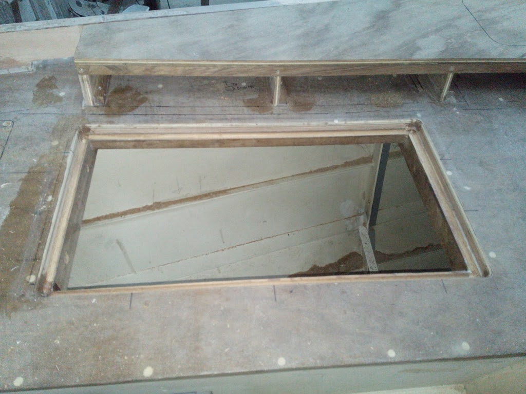
I spent some time thinking about the latter: initially I wanted to buy a ready-made hatch to fit the aperture, but there are few of a suitable size available, and anything I found which might have worked was in excess of £600 to buy. Eventually I conceded and decided that I could make my own weathertight hatch by creating a gutter with drainage and a lip to form a seal around the edge, using the standard arrangement for a ship’s cargo hatch as a model. I eventually steeled myself to cut the aperture, and managed to hit only a couple of fastenings with the saw as I went. Now, there were some scribblings in French on the underside of the hatch which implied that Guy had glued it onto masking tape in order that, once the cut was made, the hatch would just lift out as it wouldn’t have stuck to the plastic tape. Wrong. Removing the cut-out needed quite some force and chiselling, but it eventually came, only removing some of the underside in the process. There was then some fiddly joinery and routing around the edges to form the gutter and lip, and the cut-out was trimmed smooth around its edges, rounded off, and the damage to the underside made good with epoxy filler before routing the grooves for the rubber seal. I have purchased some suitable latches and hinges which will be fitted in due course, once there is some paint on the cockpit.


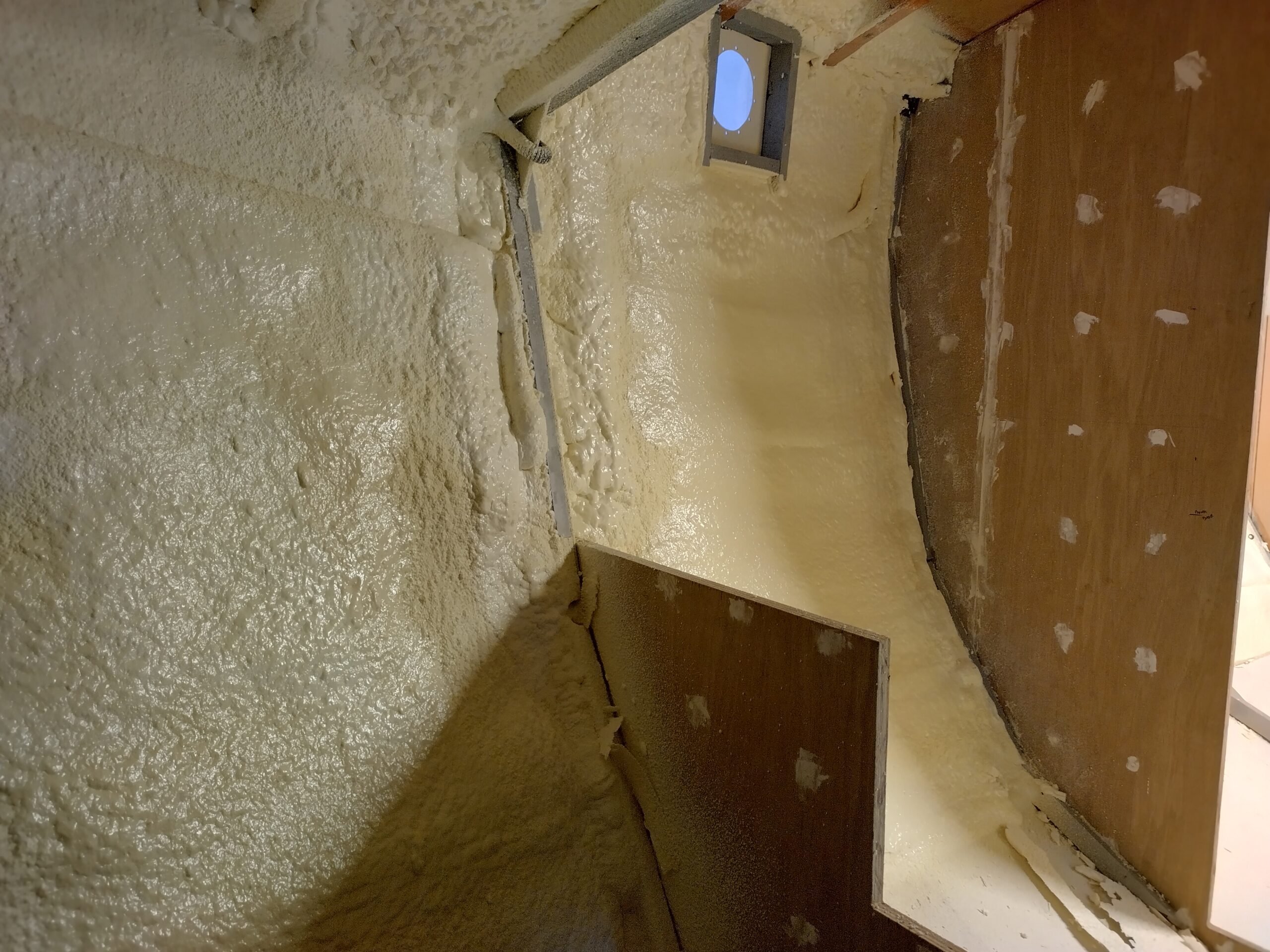
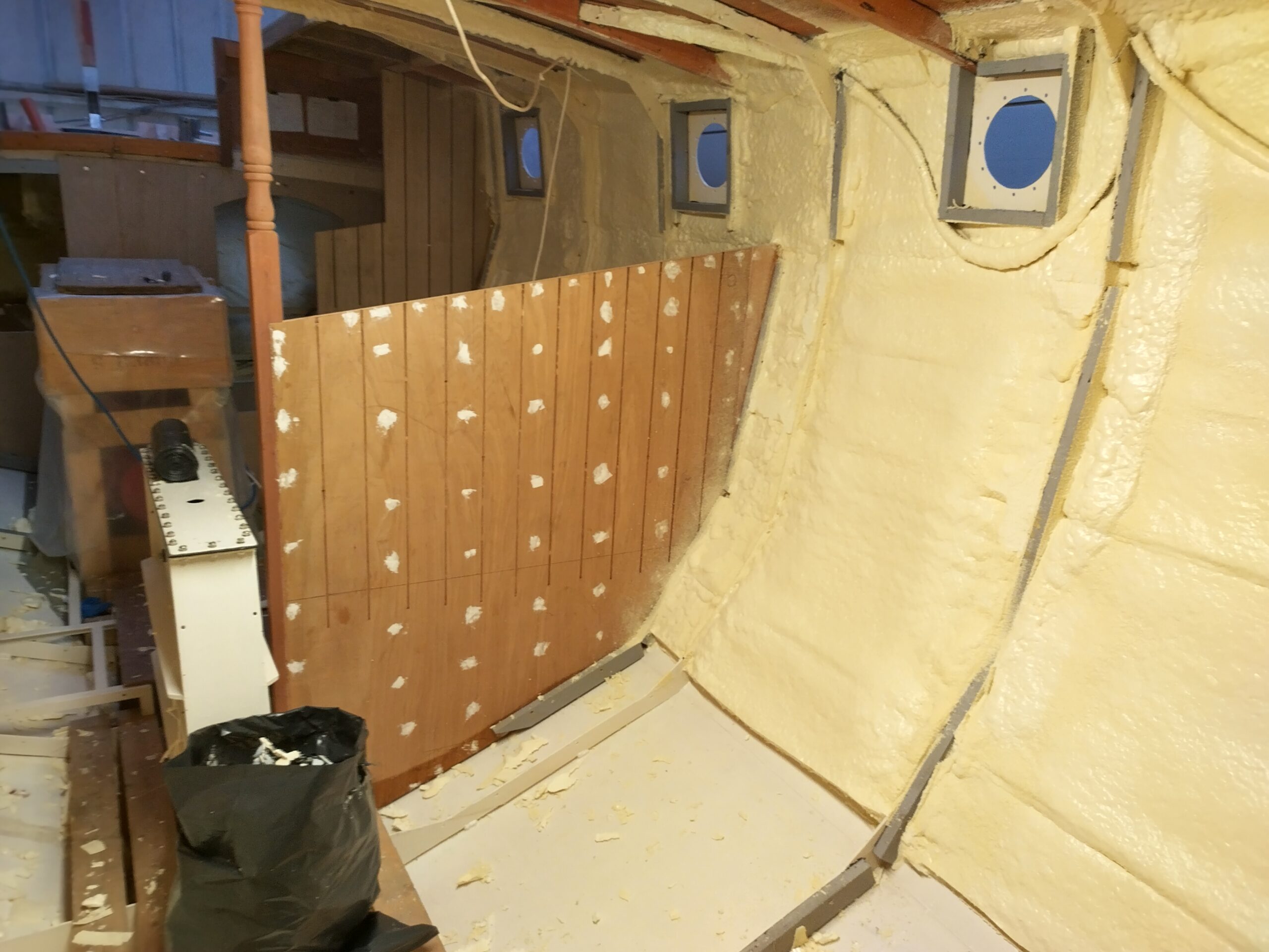
Finally the day arrived for the foam insulation to be sprayed into the hull. Having been doing a lot of sawing and routing, around the hatch aperture, there was a lot of sawdust and detritus down below, so the day before I made sure to go through the entire interior again with the hoover so the plating was all clean to allow good adhesion for the foam.
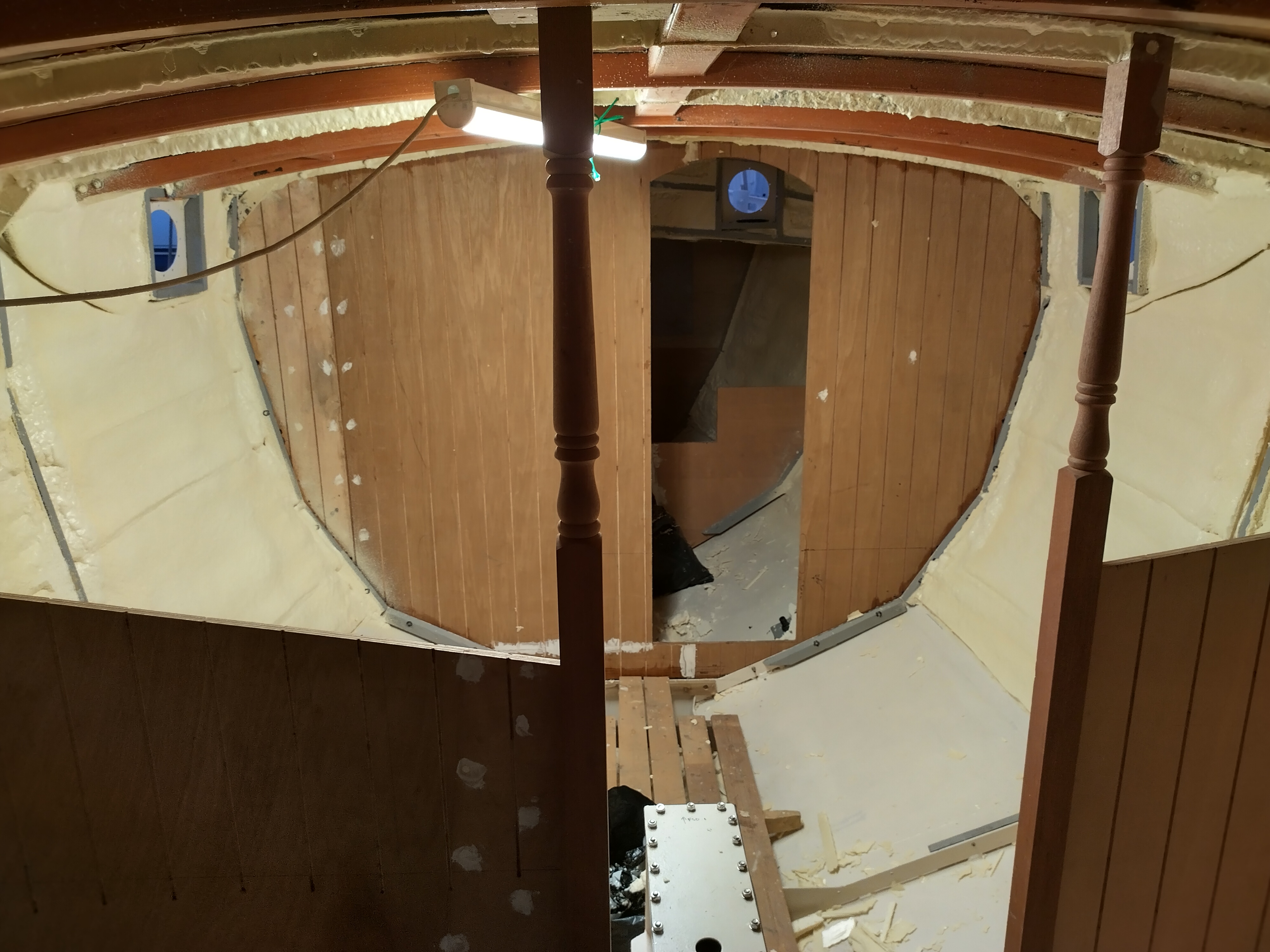
The sprayers came down the day before, having arrived in Oban, and had a look at the boat, and agreed to be on site at 0800 the following morning to start work. This they did, and first of all went through the boat masking up what they could before starting. Then the spraying started in earnest. I had some sympathy for them, certainly whilst working in the bow and stern spaces, as I had enough experience of my own doing unpleasant work in tight spaces… Whilst they were spraying, I had not very much to do, just hanging around monitoring their progress by staring through the portholes. Once they had finished I went down to check on their work, found a few spots they’d missed, which they filled in, and once they’d removed what masking they could, they left. It had only taken them the morning, so in the afternoon I began the challenging task of tidying up, trimming and fairing. The coverage was far from even, so there was a reasonable amount of trimming and fairing to be done, and the bottom edges of the foam had covered over the masking tape they had laid, so needed to be trimmed back. For trimming the edges I found that a 4″ paint scraper sliced through nicely, and the strip would then come away easily. Trimming high spots was best done with a nice flexible wood saw, with which I’d try to cut away as much as possible, before fairing back with my mini-surform. Needless to say this took some time and produced quite a mess of trimmings (like broken meringue) and dust (like grated parmesan), and I got covered. Definitely a job to do wearing a proper dust mask! There was also a fair amount of overspray around the edges of the bulkheads, on the deckhead and wooden deck beams, which needed to be removed with a sharp chisel. All in all it took me 4 days and filled 6 black sacks with debris before the foam was fair, all the frames were clear and overspray cleaned up where necessary.

This pretty much brings us up to date – I think you’ll agree there has been a fair amount of progress – and now it’s time to go back to sea for a bit. I’ll be joining Pelican in Dartmouth with this year’s new batch of Ocean College students. I’ll be taking them down to the Canaries, Cape Verdes and then across the pond to Antigua before returning in December for more work on Serchthrift, and Christmas en famille.
Dear Chris,
It’s nice to see you are making progress on your ship. I would like to wish you continued good fortune, merry Christmas and a Happy New Year.
All the best,
Mickey (from Ocean College)
Good to hear from you Mickey, hope you’re well! Merry Christmas and a happy new year to you.
Chris