NOW WE CAN REALLY GET STARTED!
Greetings from warm and sticky Costa Rica, as I and the crew of Pelican of London await the return of our Ocean College students from their adventures ashore. As I write, sitting in the open air bar of the marina which has been looking after us for the past few weeks, it is strange thinking back to the near-freezing temperatures I left only two weeks ago!
So far everything that I have achieved, and looking back over the past 18 months actually there is quite a bit, has seemed like a mere prelude to the actual task of fitting Serchthrift out as an ocean-capable, expedition yacht, and floating home. All the painful and uncomfortable steelwork, the second layer of ply on the deck, the race against curing epoxy (even in chilly October temperatures), the grinding, sanding, drilling, vacuuming, cutting, welding and, above all, thinking and planning, have finally led me to the point where I can actually start building an interior and making her a yacht.
So arrived the exciting day in mid-December, a few days of recovery after flying home from Antigua after a very dull and windless transatlantic crossing in Pelican, when I was able to slide the first sheet of ply off the pile which has been sitting under the bow for over a year and start shaping the first of the bulkheads for installation. The sequence of fitting out needs to fit around the planned application of sprayed foam insulation inside the hull; hence my having painted only the bilge area in the autumn, the remaining area of the inside of the plating being set to be completely covered in foam (which itself acts as a protective coating). Therefore the bulkheads and half-bulkheads which are going to form the basis of the internal structure and furnishing need to be firmly secured to the steel frames before they get covered up. Also required will be timber cleating on each and every transverse frame into which the timber hull lining can be screwed, and a certain amount of the ship’s wiring (or at least conduit) and other systems needs to be planned and installed before slathering the inside with foam.
I decided that the bulkheads were the best place to start, and where better still than the biggest of them all, the main bulkhead separating the saloon from the forecabin and heads. This and the bulkhead on frame 2 (coincident with the forward face of the coachroof) are both large enough to require laminating from multiple sheets of plywood. The main bulkhead took four whole sheets of 9mm ply, laminated in two overlapped layers to make a total thickness of 18mm, which prevents the flimsy (but probably just adequate) feeling of a 12mm bulkhead.
The first stage of the process of building a bulkhead is to make a full-size template. If you try and take the dimensions off the plans and lay them down straight onto a sheet of ply you are asking for problems, and in my case this is compounded by the fact that the drawings are in some cases so faded you can barely make out the lines. Last time I was on leave I spent a good half-hour with Alastair, one of the yard hands, a bottle jack and my builders’ spirit level, to ensure the boat was absolutely level and upright. That way I can use a spirit level to ensure the furniture is square and level – a luxury I didn’t have when I refitted Meander, and regretted as it makes things so much more difficult.
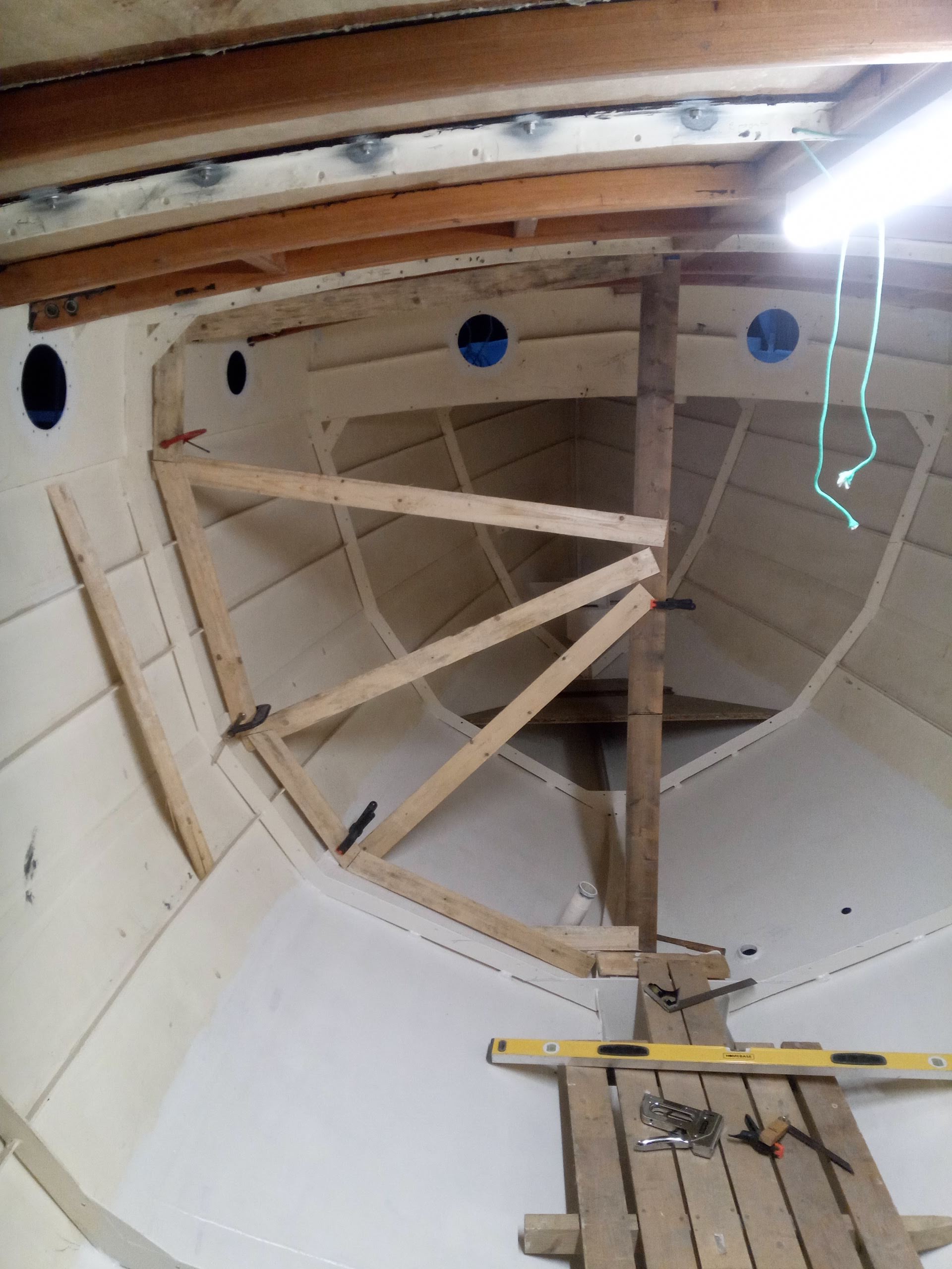
My method for building up a bulkhead template would probably not be accurate enough for an artisan-built wooden boat, but given that the interface between bulkheads and frames / hull is all going to be encapsulated in foam, it is sufficient, and is also improving with each successive bulkhead. First of all I take one of my multi-purpose but reasonably straight lengths of ¾” x 4” softwood (these were bought in order to make a framework for the temporary cover I used when the boat first arrived at Balvicar nearly three years ago, and now are doing duty as straight edges, temporary floorboards, battens for weighing down the plastic cover over my pile of ply, and sturdy centreline uprights for bulkhead templates), and secure it with clamps plumb on the centreline (actually slightly offset so one edge is on the centreline). I then work steadily up from the bilge using some scrap strips of ¼” x 3” dunnage with reasonably straight edges, which I found on the scrap wood pile in the shed, following the contours of the plating as closely as possibly, mitring the joins and stapling them together. As I work my way round I add some diagonal bracing to the centreline upright to make sure the template remains stable when handled. Once the rough outline is assembled, which by necessity does not mate up exactly to the inside of the planking, due to the slight curvature as well as the presence at intervals of longitudinal stringers in the upper two strakes, one marks the exact profile with a device called (or which I call, at least) a joggle stick. This is a length of wood about 18” long, again with reasonably straight edges, which has a pointed end, and “joggles”, or right-angle triangle-shaped notches taken out of one edge at regular intervals. This is placed on the template, with the pointed end against the planking (or a consistent distance off if a gap is required), so that one of the joggles lies entirely on the template. You then trace the outline of the edge of the stick and the joggle (and annotate which joggle you are using, if necessary) on the template, so that when the template is taken out and laid down on the sheet of ply, you use the joggle-stick, lined up exactly with your markings, and mark where the point of the stick falls on the ply. All your marks are then joined, using a spline to form a curve if necessary, and there you have your bulkhead’s outline marked out full-size. The joggle stick is also used to mark the location and extent of intrusions such as the stringers, and the position of the deck edge, etc., and you get a pretty accurate pattern.
Having constructed the template on one side only, before removing it from the boat for marking and cutting the ply, I flipped it round onto the starboard side to check how symmetrical the boat is – well done Guy, you did a pretty good job of lofting and she’s nice and symmetrical!
The challenge with the main bulkhead was always going to be its size – in order to fit it down the hatch (or more accurately, the doghouse aperture), it had to go into the boat in sections. Before going too far with cutting and laminating therefore I did a quick back-of-envelope plan of the sequence in which I would construct the beast.
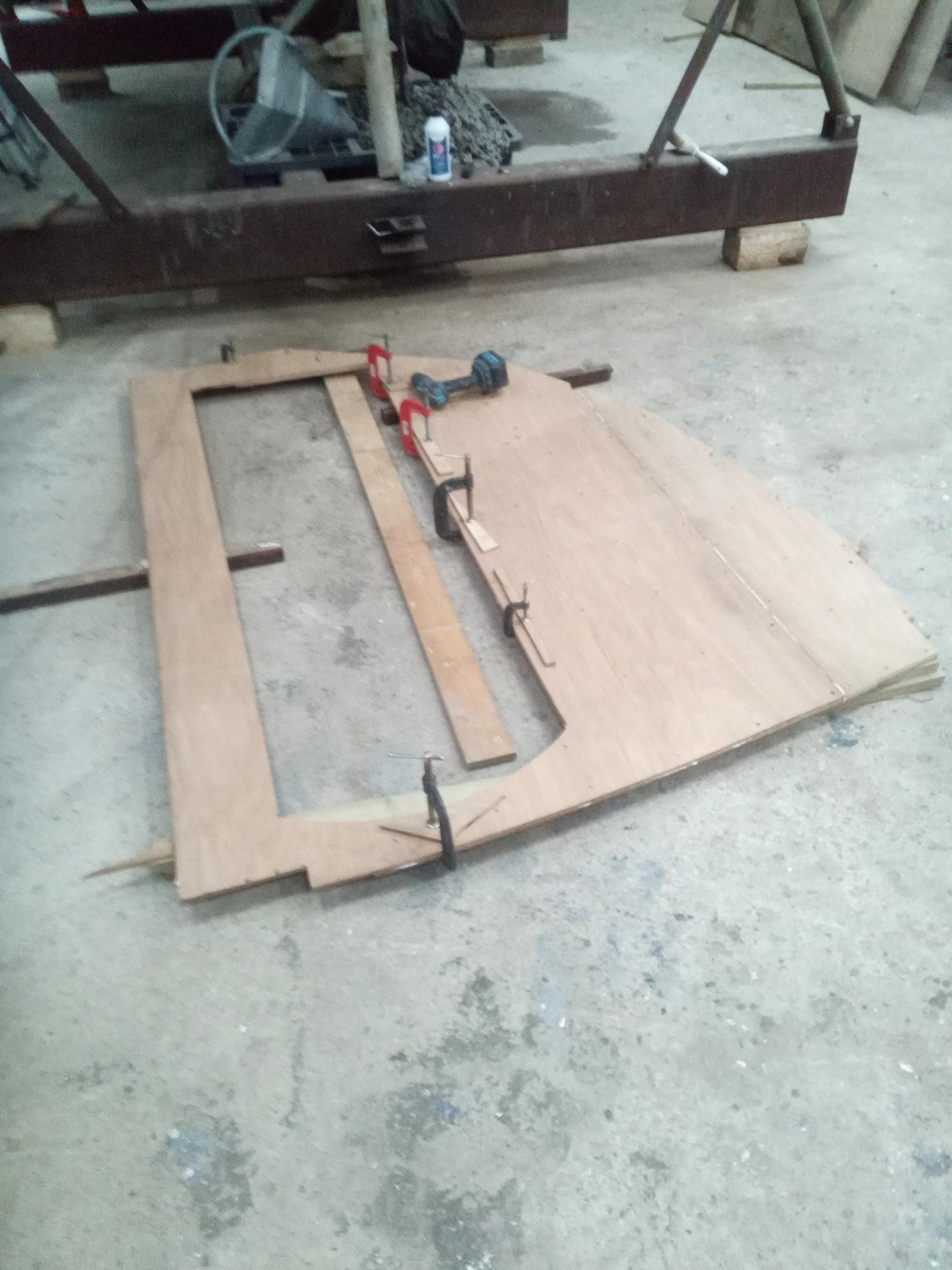
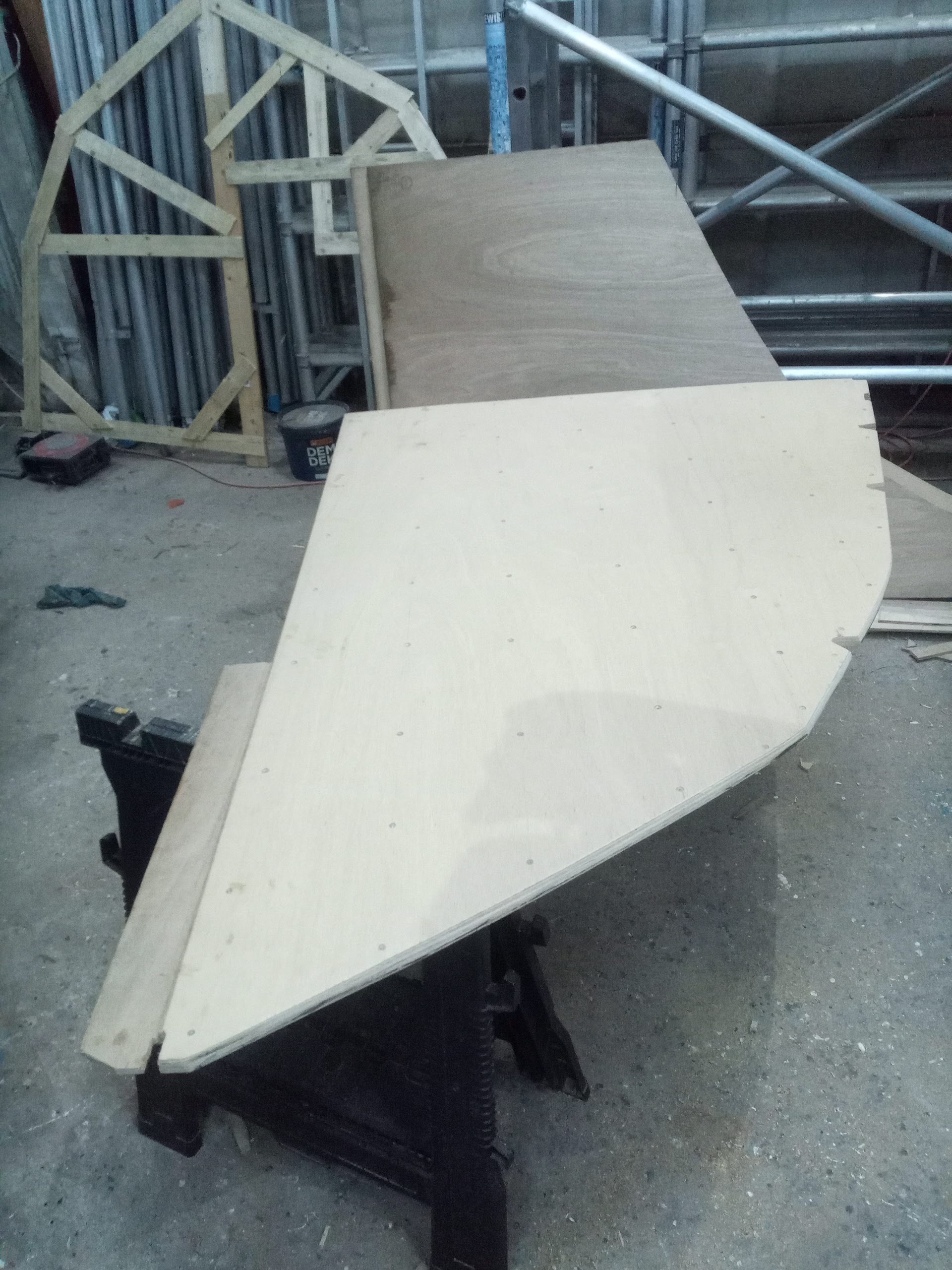
So, having decided how to divide up the sheets and ensure a good overlap of the two layers for strength, I set about marking and cutting the individual pieces of the puzzle, the largest of which were 4 feet wide (the full width of a full sheet of ply) and about 7 feet long / tall, and therefore challenging to handle. This was compounded by the copious quantities of splinters available on newly-sawn edges to catch the unwary hand as one moved the sections around. Amazingly it took about one and a half bulkheads before I thought about wearing gloves to do this, at least until I got to the stage where I had planed and sanded the edges!
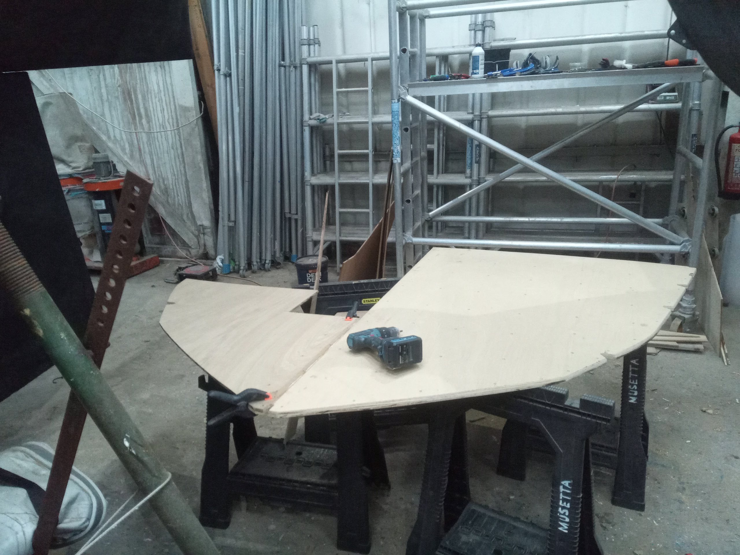
Once all the sections were cut, using one side to mark out the other side, the same profile thus being cut out four times, I laid them out on the shed floor to ensure everything mated up correctly, temporarily screwing and clamping the layers together so that I could mark out and cut the door aperture (this had to be done at this stage so I had a means of attacking both sides of the bulkhead during the process of fitting it. This done, I started glueing the sections together until I ended up with three pieces: the entire starboard half (incorporating the door cut-out), the partially laminated port half, and separately, the last sheet which would finally overlap on both sections and bring the two together once in the boat. This latter, in fact, had to have its very lower 6” or so cut off, as the bulkhead was (unconventionally – more on this in a second) to be fitted forward of frame 3, and I would never get the last part into place in its full height, once the other two pieces were bolted in place to the frame. The little bottom wedge went in first, slipped in between the frame and forward laminate of the bulkhead, then it created a wedge on which the main part could rest as I got the screws into it to hold the laminates together whilst the glue set.
However, I’ve skipped a couple of stages. First of all, I lifted everything into the boat (a 5-foot by 7-foot piece of 18mm ply is quite a challenge to lift up the 8 feet or so onto the deck and the lower down the hatch and manoeuvre past the engine and centreboard case into position) and dry fitted it. It was at this stage I had a design wobble. The intention was to attach the bulkhead to a row of tabs which Guy had welded in about 4” forward of frame three. However, with the sections of bulkhead clamped into position on these tabs, it became evident that this was obstructing the steel 2” threaded standpipe which I will be using as the heads / black water tank outlet, to the extent that it would be impossible to screw on the seacock or subsequent fittings. Some head-scratching ensued, during which I considered the consequences on the saloon layout if I made a cutout in the bulkhead to allow access to the seacock. This was not a desirable option, so I considered cutting the pipe flush and using a reinforced nylon through-hull fitting (as I am using extensively elsewhere), but access would still be tight, and this was discounted. Eventually I decided, after reviewing my general arrangement drawings and doing some more measuring and head-scratching, that I could afford to move the bulkhead aft by the few inches between the tabs and the forward side of frame 3 without losing too much length from the settees, so they could still be used as occasional sleeping berths without the occupant needing to be vertically-challenged. Fortunately, with such a small gap between the two positions, the bulkhead was still the right shape to fit and overlap the frame sufficiently to get bolts through the edges.
Dry fitting big wobbly bits of ply 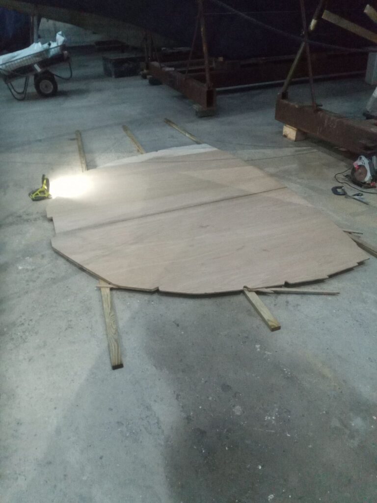
Laying the sections out on the floor 
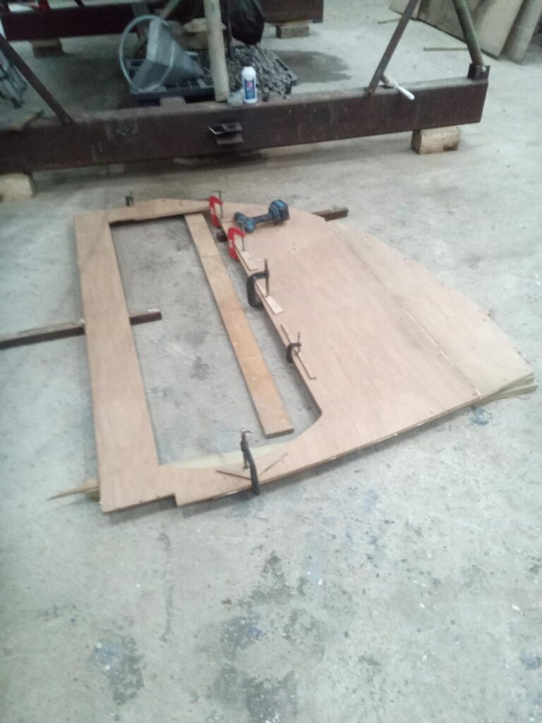
Cutting the door aperture and glueing 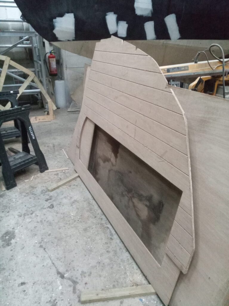
Stbd half ready to go in, complete with “T&G” grooves 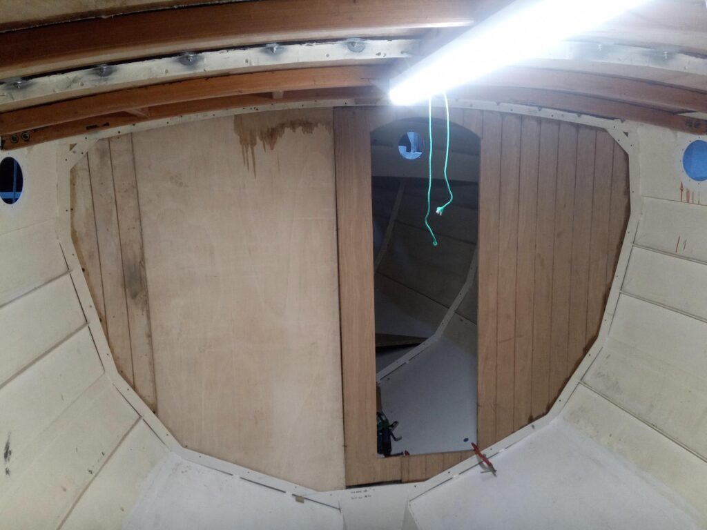
Fitting the pieces together 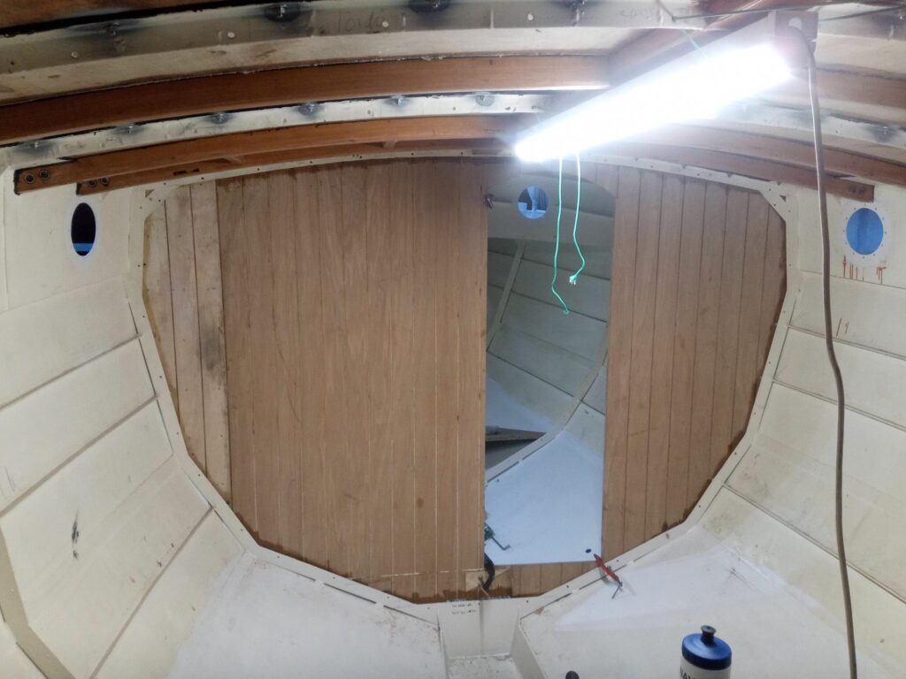
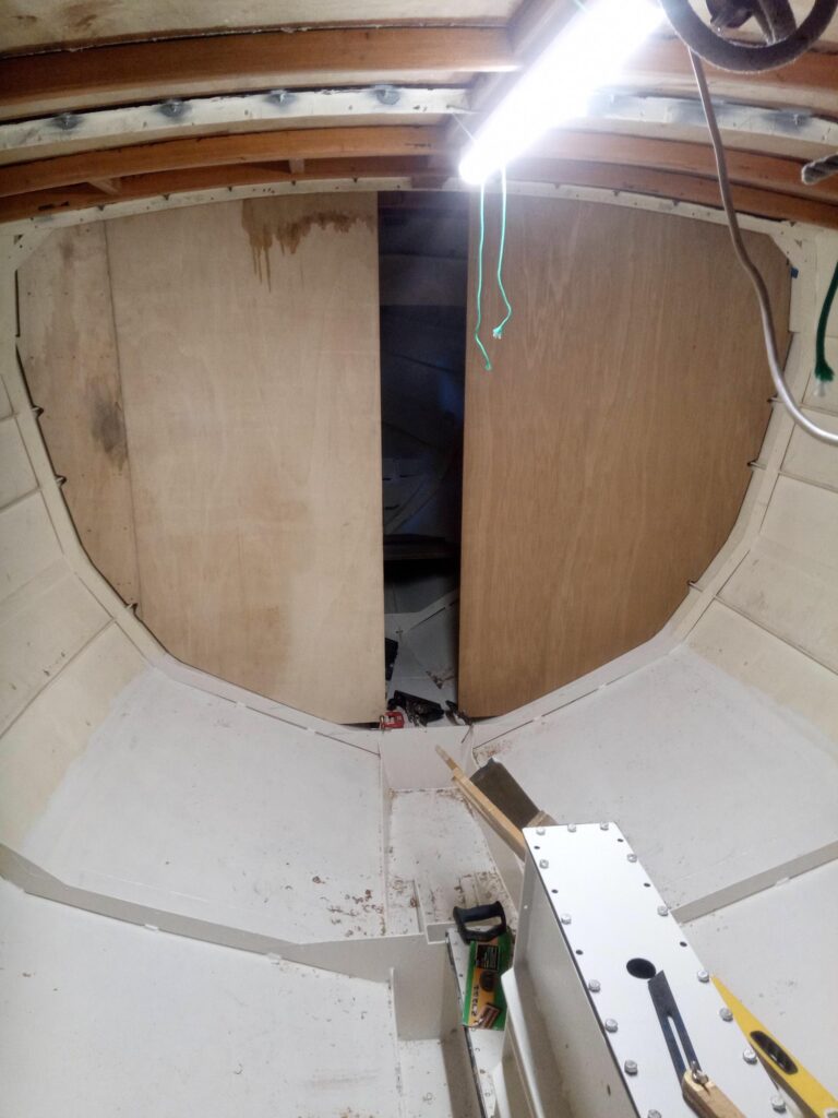
The final fit – note the small piece at the bottom which had to be cut off the centre aft laminate in order for it all to fit together in situ.


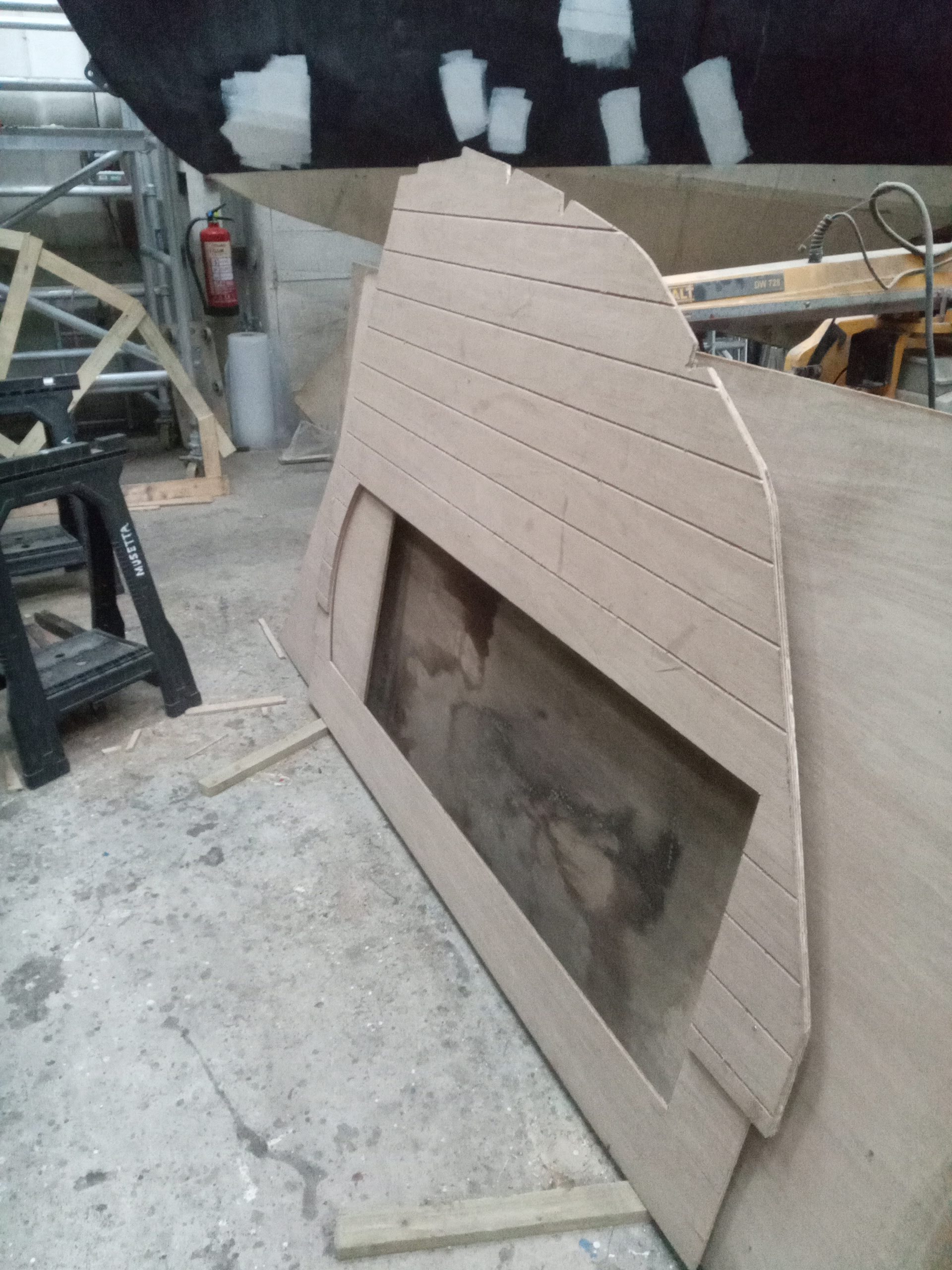

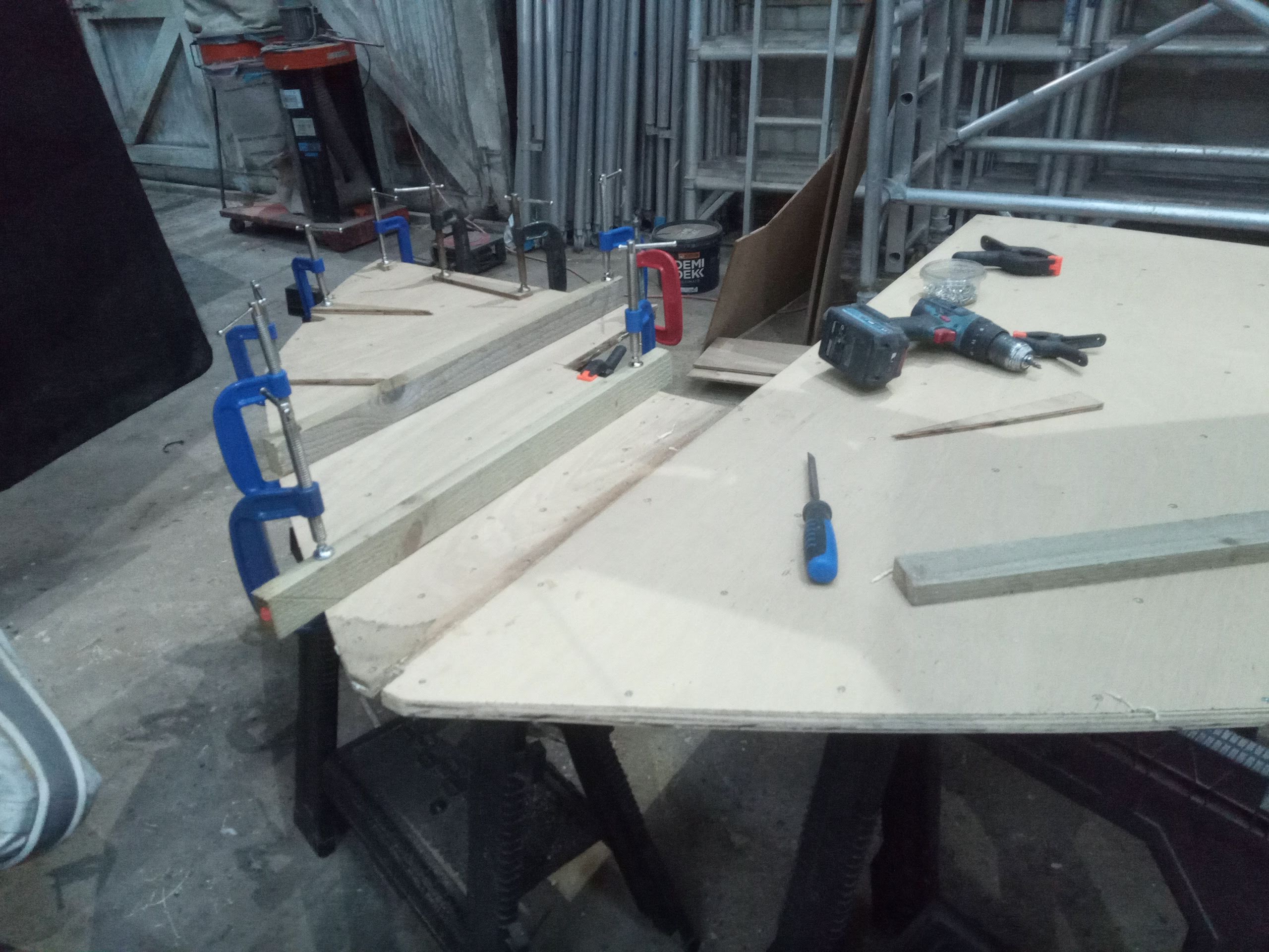
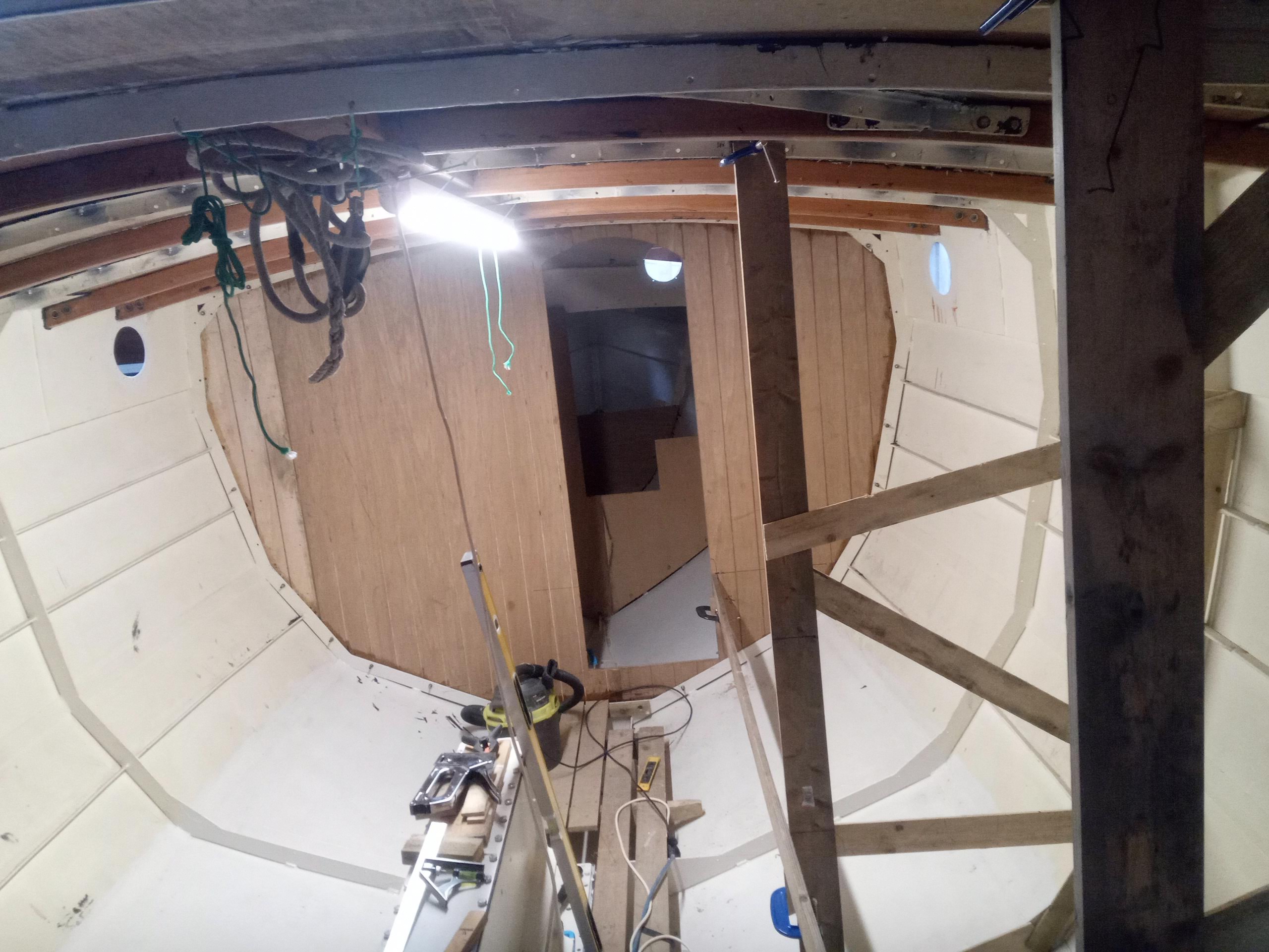
Once I’d made this decision, and clamped everything in the new position to double-check its fit, I took everything back down to the shed floor for the final woodworking touches. Firstly, the edges of all the pieces needed to be tidied up, planed and slightly bevelled to conform to the contour of the hull (not so important with the main bulkhead as due to the shift aft it was slightly undersized anyway, but more important with subsequent bulkheads), and sanded to remove the splinters and any roughness. I also wanted to rout v-grooves in the aft face in order to imitate the traditional appearance of a tongued-and-grooved timber bulkhead. The Wylo does, after all, have a traditional look, even when it is junk-rigged, so its fit-out will be consistent with the boat’s overall appearance. This done, the final pre-fitting step was to coat the edges / end grain, and the surfaces which would “fay” (overlap) with the steel frame (a strip about 2” wide around the entire aft side of the edges), with epoxy resin, to prevent any water ingress and subsequent risk of rot or delamination.
The next day then was assembly day. The pieces of the bulkhead went back up into the hull (my muscles definitely complained the next day) and the two partially pre-laminated sections were clamped in place, trued up and drilled for the bolts. I then removed them again, and spread bedding compound on the faying surfaces before refitting the sections and bolting them in place loosely. Then the small bottom wedge of the final sheet went in, similarly treated on the faying surface, and glued and screwed to the forward laminate, before the final sheet went in, glued and screwed again, to join the two larger sections with a 12” overlap at the centreline. The entire assembly was then bolted with m8 countersunk bolts, most of which are overlength in order to allow the addition of the timber cleating (for the hull lining, remember – keep up!) on the other face of the frame, using the bolts to secure it.
This whole process had taken several days to achieve – a slight delay having been caused by the issue of the heads outlet pipe – and Christmas was soon approaching, my parents being due to arrive on the 21st December, and some Christmas food shopping requiring my attention before that event. I did, however, have sufficient time to template, mark and cut the frame 1 dwarf-bulkhead, which separates the cable lockers from the foremast step. This little chap I laminated from two layers of 9mm ply – not because of its size, but more because I had some 9mm spare, and the 18mm was still buried under several sheets of 9mm on my pile! I did not have time to fit this, but left it pretty much ready to go in after the Christmas festivities.
Christmas was a bit of a hiatus in boatbuilding activities, as the cold weather was not conducive to parental assistance in the shed, although we did go down one day in order to use their assistance to mark the new waterline. This needed doing because when we moved the boat by water from Balvicar to Kilmelford, she floated pretty much exactly on the waterline which had previously been painted on. This would have been fine if she was finished, but as it is, the extra weight of the internal fit-out, additional superstructure (doghouse and cockpit coamings) masts and equipment would bring her considerably down on her marks. Therefore I decided to move the waterline up by 4” to allow for the finished weight, as well as allowing for the weight of crew, bunkers and stores and the inevitable middle-aged spread which any boat gains as cruising season rolls into cruising season…
To achieve this, I had already marked a datum on the transom, and we moved progressively forward on each side with a clear flexible plastic hose full of water. The tube was adjusted until the water level at one end was coincident with the datum mark, and the other end placed against the hull, the water level of course at the same height as the other end, which allowed us to mark the hull. We moved forward step by step, mark by mark, until we reached the stem, and then started again at the transom on the other side. Despite the potential for inaccuracy introduced by our method of using a short length of hose and using the previous mark (rather than the datum) for each successive mark, we only ended up with about ¼” discrepancy at the stem, if that, which can quite easily be “fudged” out of existence!
The reason for doing this now is that, prior to insulating, the above-waterline through hulls need to be in place, and before fitting these I want to apply at least the first coat of topcoat on the topsides, so I might as well know where the waterline is going to be before doing this so I can paint to the new waterline and not waste expensive topcoat! It will also be yet another external indication to the casual observer that progress is definitely being made on the steel hulk in the corner of the shed! To that end also, just before the Christmas break I ordered the through-hulls and seacocks in readiness, although there was a slight hiccup here in that the New Zealand manufacturer of these fittings, Tru Design, had suffered a warehouse fire, and my chosen UK stockist had only one of the numerous parts of the order in stock. This they only told me after taking my money… However, on contacting another stockist I had more joy, and they were only missing one, not absolutely essential (at this stage at least) part of the puzzle.
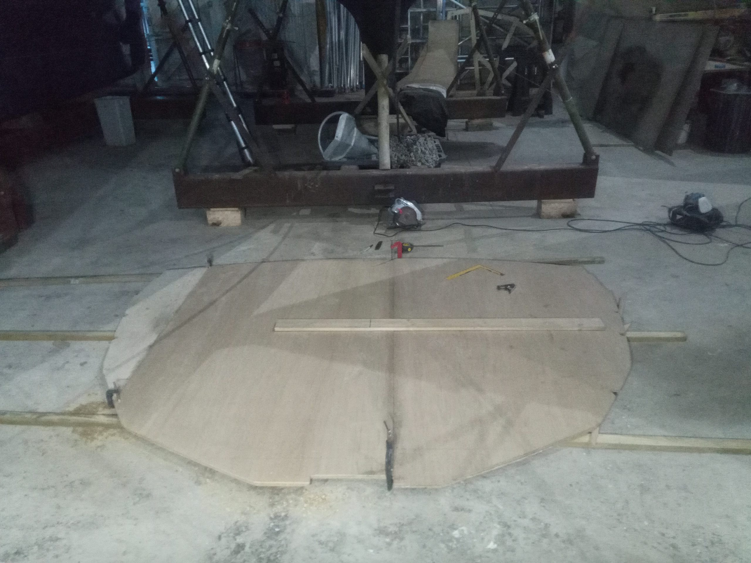
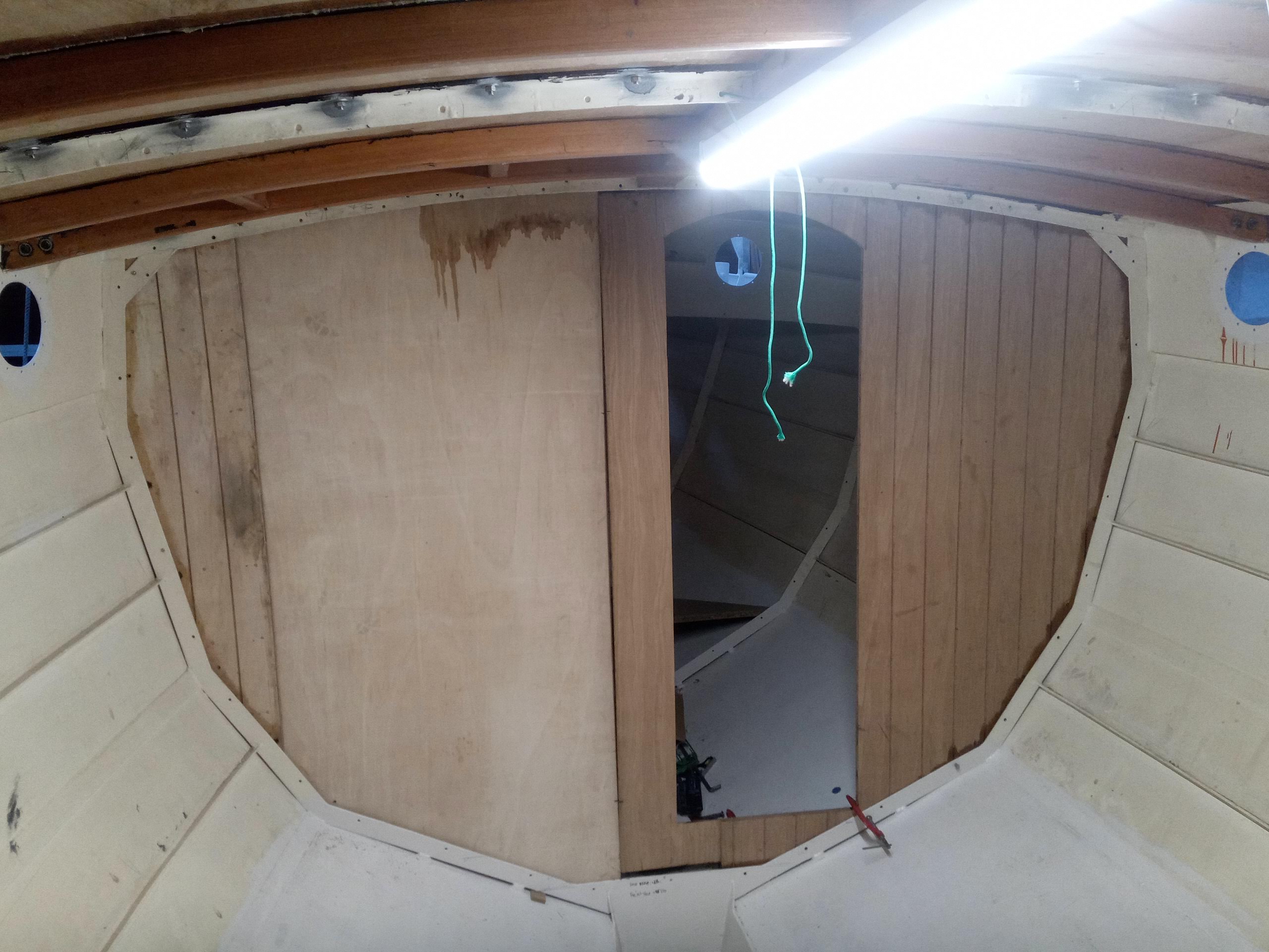
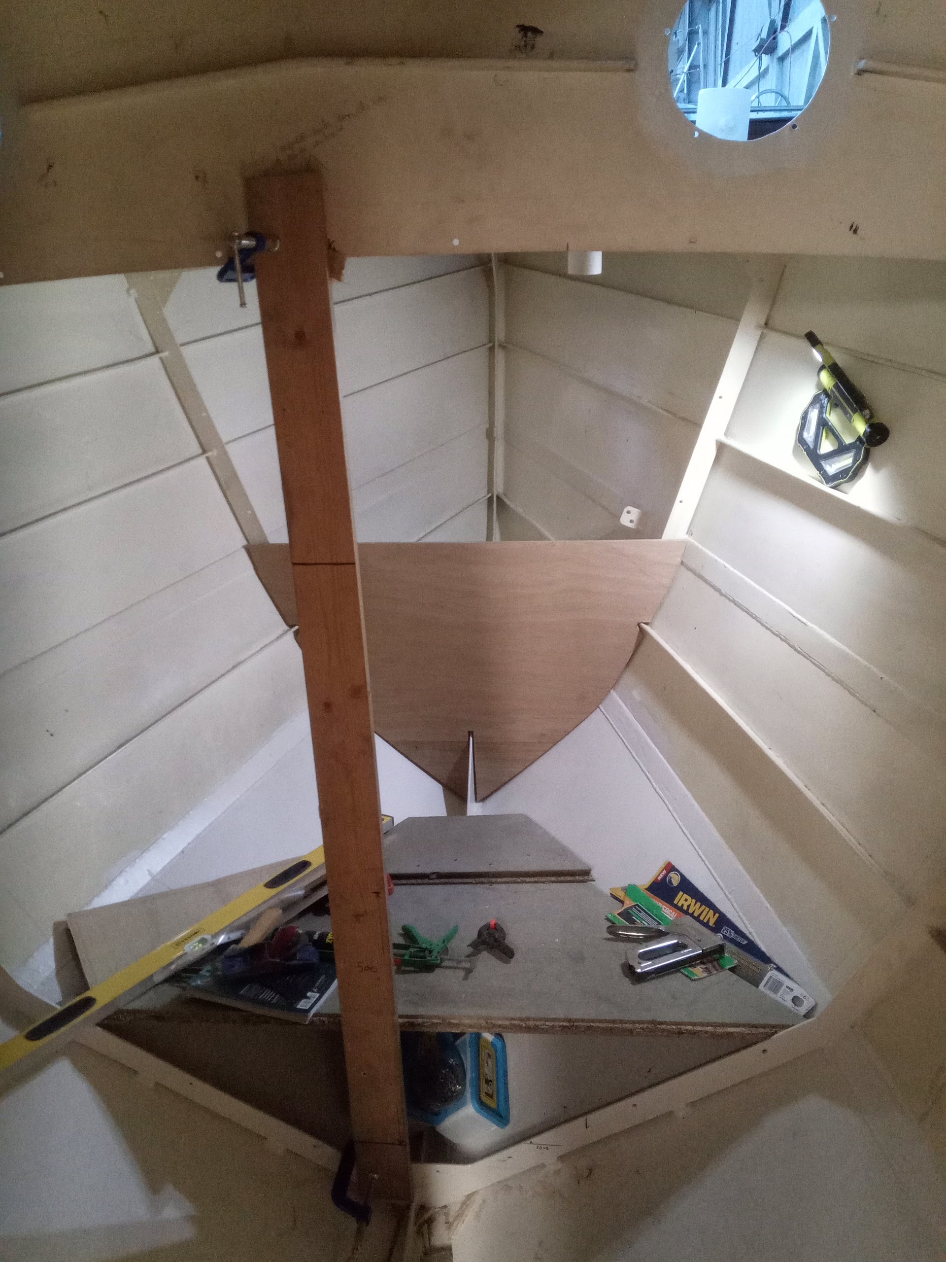
Christmas came and went, and a very merry time was had by all, my culinary skills being put very firmly to the test, and before we knew it I was back in the shed and making the template for the frame 2 bulkhead, which is about ¾ of a full bulkhead. This forms the forward partition of the heads compartment on the port side, then on the starboard side is cut down for about 15” from the centreline to allow access to the cable lockers and stowage in the forepeak, whilst rising further outboard to form the support for the base of the forward berth (a single), which will have a fold-down workbench over the its head, under the forehatch and forward part of the coachroof, with standing headroom.
This again is a laminated bulkhead, but much more easily manageable, and it could be manoeuvred into the boat in one piece, meaning it could be fully assembled on the shed floor.

Frame 1 dwarf bulkhead being dry fitted… 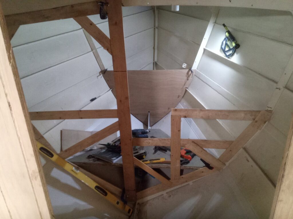
And then wet-fitted, with frame 2 bulkhead template in foreground 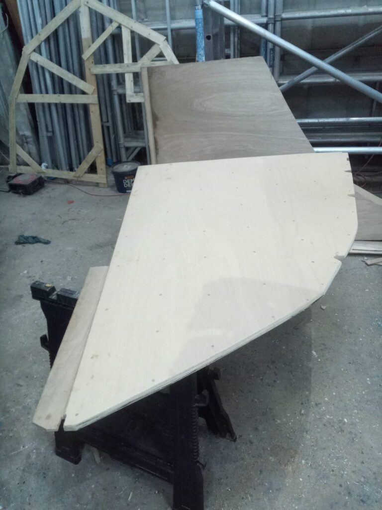
The bigger half of frame 2 bulkhead laminated up – note overlap for joining to the other half 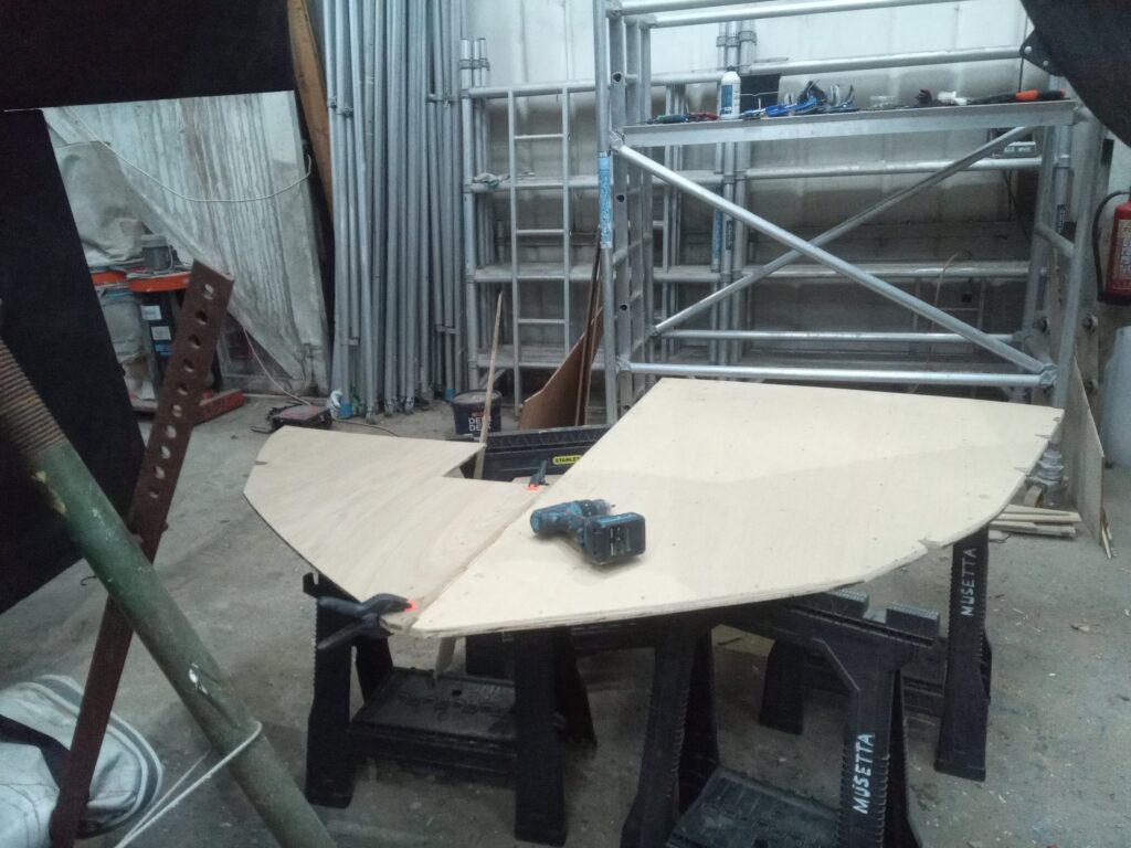
Making sure the halves fit together… 
Then glueing up 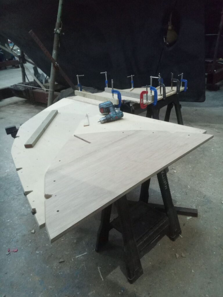
This one-s small enough to go in in one piece… 
And dry fitting…


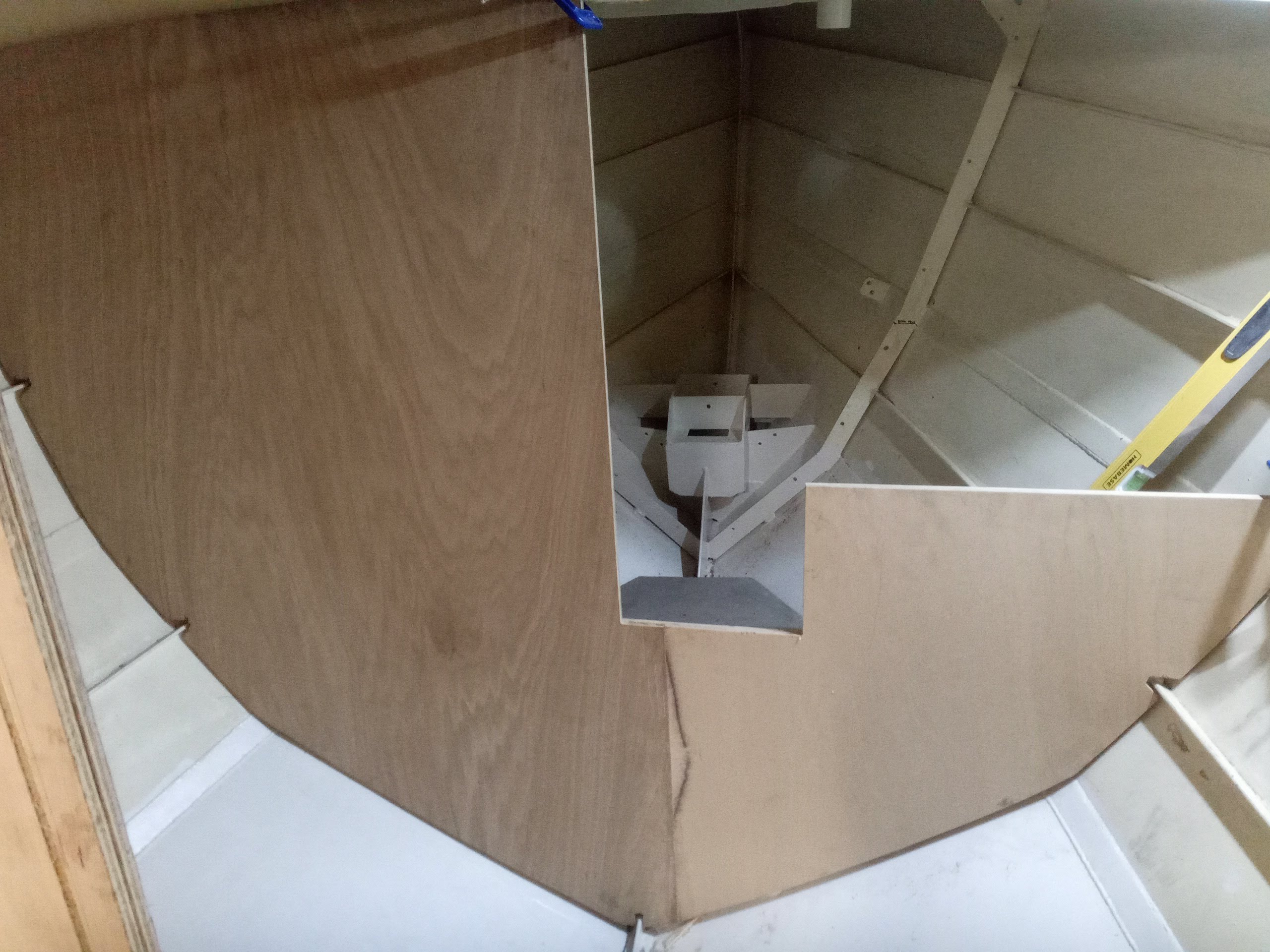
Once this was complete I fitted both it and the frame one dwarf bulkhead, again bedding the edges and frames in poo and through-bolting with over-length bolts, then move aft into the saloon to start templating for the partitions making up the remainder of the furniture and accommodation. Starting on the starboard side, I first templated the half-bulkhead which would partition off the aft cabin from the saloon. I was getting quite quick with this process now, so decided next to mock up the inboard edge of the starboard settee to work out exactly how I would set out the chart table. Again I decided on a slight deviation from my original idea of using the aft end of the settee as a navigator’s seat, preferring anyway to stand over my full-sized admiralty chart, so decided on a simple half-bulkhead extending up as far as the deck-edge on the outboard edge, sloping down slightly towards a hardwood turned pillar supporting the inboard edge. This will match the forward galley partition and keep the main cabin open and airy. Once the concept had been approved, I took the two templates to the floor, pulled out a (now accessible) sheet of 18mm ply and cut both from the one sheet. No laminating was required here, just cutting, planing and sanding the edges, routing v-grooves on both sides (at least where there would be no furniture hiding the effect), epoxying the edges, and then fitting. The only real snag encountered with these was the annoying habit of the frame 6 (aft cabin) bulkhead slipping down into the bilge every time you tried to adjust it a smidgen.

A view forward, with frames 1, 2 and 3 bulkheads visible, as well as the template for frame 5 stbd 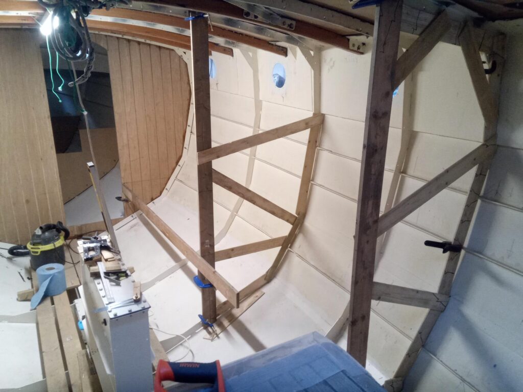
Frame 5 stbd template – note the plank being used to mock up the edge of the stbd settee 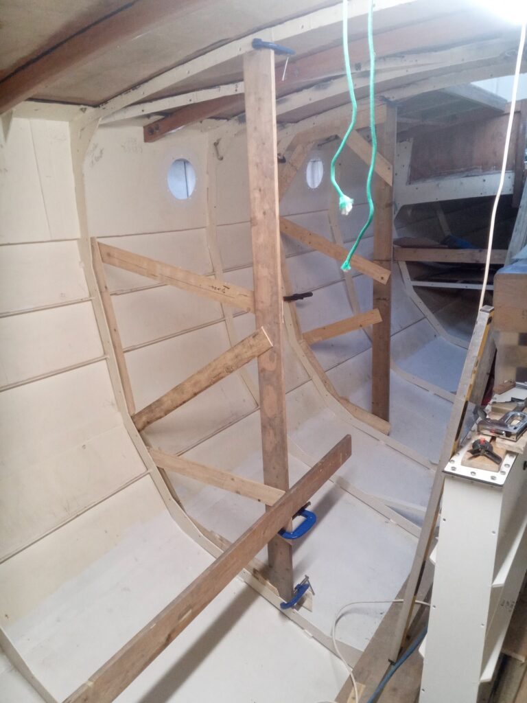
Frames 5 and 7 stbd templates 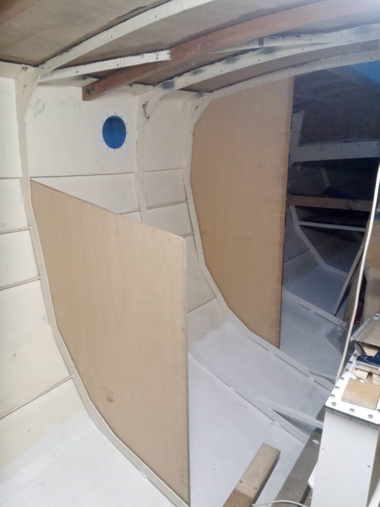
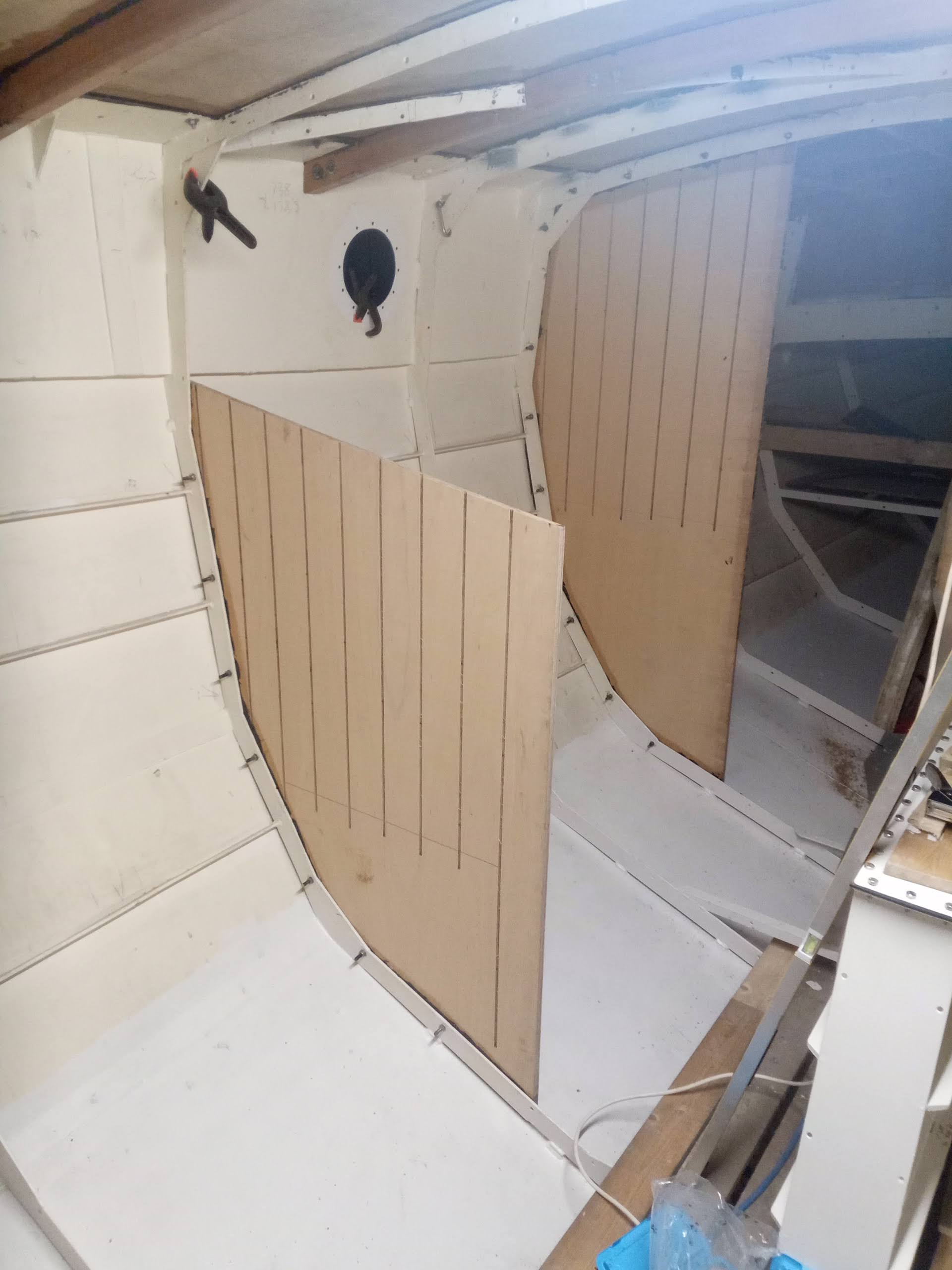
Frames 5 and 7 half-bulkheads dry-fitted… 
…and fitted, complete with “T&G” finish, where it will not be hidden by furniture.


One further small job which I had been working on during this period was to prepare the aperture and fairing for the echo sounder transducer to be fitted in due course. There was a second steel standpipe for a hull fitting on the stbd side opposite the one I will be using for the heads outlet. If left as it was, it would have projected through the sole in the passageway forward of the main bulkhead, outside the heads door, so I decided early on to crop it almost flush to the inside of the plating, and as it was vertical (rather than perpendicular to the plating) it lent itself perfectly to being the hole through which the transducer could pass. Unfortunately, it was a 2″ BSP pipe, and the transducer thread is 18mm diameter, so somehow the hole needed to be made smaller. This could, admittedly, have been done by welding a blank onto the cropped top of the pipe, but I decided instead to fill the aperture with epoxy resin, well thickened with colloidal silica powder, and pressed in firmly against a smooth, parcel-taped blank wedged tight up to the outside of the planking, forming a smooth exterior surface. Once well-cured, I drilled this at the correct angle to the required diameter, so now it is ready for receiving the transducer, which fits into a fairing bulb and through the plating, with copious quantities of bedding compound, and a nut on the inside nips up the assembly tight.
By this stage my leave was drawing to a close, and I was preparing for my flight out to Costa Rica to join Pelican again, so there was just time after fitting the last two bulkheads to tidy the boat and the shed floor, leaving just the two galley partitions to do before moving onto the next task, which will be the cleating. The hull cleating will be fairly straightforward, but before tackling the coachroof sides I need to consider how to box in the porthole apertures so they are attractive, but leaving as little bare steel to accumulate condensation as possible. I have considered both wooden box “returns”, which could employ some of the reclaimed teak I have in my stack, and plastic pipe sections. The former will be more attractive, and easier to fix to the rest of the timber cleating, so will probably be my preferred choice. This has to be considered now and fitted prior to the spraying in of the insulation, as will the bulk of the electrical cabling, or at least conduit for it, in order to conceal it effectively behind the linings. I have some novel ideas for the lighting cabling, which hopefully will reduce the amount of cable required and allow the future addition of more lights if necessary, essentially using an oversized 12V “ringmain” around the coachroof sides, with spurs taken off for individual lights using special connectors which cut into the insulation of the cable without the need for chocolate block, splices or anything like that. I will also need to consider cabling for nav lights, radio aerials and other electronics (although may not need to fit it all at this stage) before I can call in the sprayers.
Finally, in amongst all this excitement I have been considering my future career and the direction I want it to take from here. At the time of writing this is still a dynamic situation, but I will have to come to a decision soon, and will let you all know what comes to pass in due course.
POSTSCRIPT: in reference to the final paragraph above, I can now announce that I have turned down a tempting offer from the Royal Fleet Auxiliary to join them as a Second Officer in the Deck Department. It took many weeks of agonising to come to this final decision, especially with the pay and pension package which were on offer. However, having been in the world of tall ships for so long, I decided that a return to the far more bureaucratic and formal world of full-time MOD employment would not, ultimately, be my scene, and I would much rather be a large cog in a small machine, than to become once again a functionary in such a bloated bureaucracy. I also had to consider the position they were offering me, which essentially would be at a roughly equivalent level to that which I abandoned when I left the Royal Navy in 2005. I feel much more relaxed now I have made the decision, and though I may be poorer financially from it, I am a great deal richer for the experiences I continue to gain and the relationships I develop in the little world of tall ships.
I really enjoy your blogs Chris. Takes me back to my youth when I was an apprentice shipwright. ?
Can’t wait to see the finished article.
Stay safe.
Just please don’t look too closely at the standard of workmanship! I’m still learning!
I’m pretty sure it’s fine. I know you are thorough, and not a bang it and bodge person. ?