Bulkheads and cleating continue (and power tools conspire against me)…
Once again it has been a long time since my last update – what was going to be a 6-week trip on Pelican before returning to the UK and a possible job-change, turned into a marathon 3-months, with the final month spent preparing the new Seas Your Future vessel, the schooner Fridtjof Nansen, for her delivery to the UK and subsequent refit.
I finally arrived back home in the first week of April, and so have been hard at work since then making further progress on the boat. When I left, I had completed five of the originally-planned seven bulkheads, with just the galley partitions to fit. Whilst I was away I had also had delivered the specially-turned pillars which were intended to reinforce the edges of the fwd partitions for the galley and chart table, so these were waiting for me when I got to the boatyard. It was well worth the cost of getting a couple of pillars nicely turned (I went to a stair parts manufacturer from whom I had ordered a smaller spindle for Meander’s refit back in 2010), as they will create a nice focal point in the main cabin, as well as providing a hefty handhold for anyone making their way forward at sea. The one on the port side galley partition will also provide an anchor point and structural reinforcement for the centreboard winch, which will pull downwards, allowing the deckhead beams and the vertical pillar to take the weight of the board (which is a 1/2″ galvanised steel plate and weighs quite a bit). Therefore I had to consider carefully how to secure this pillar in particular, as well as how to fix the top end so the upward load is spread into the deckhead. Therefore I constructed a pad from 2 layers of 18mm ply, with a mortice cut in it to receive the top of the post, and routed a substantial rebate in one corner of the post to which I would glue and screw the edge of the bulkhead, which itself is bolted to tabs welded to the shell plating. The starboard pillar on the chart table partition was slightly simpler, not having to take the loading of the port one, but is still substantially fixed in order to assist with the overall strength of the structure, and to support any loading on the deck above. I approached this pillar slightly differently, as the partition coincides with a frame, so the pillar could be through bolted to the ring frame top and bottom, and the bulkhead I let into a routed groove rather than a rebate, making for a very attractive finish, completely hiding the edge of the ply.

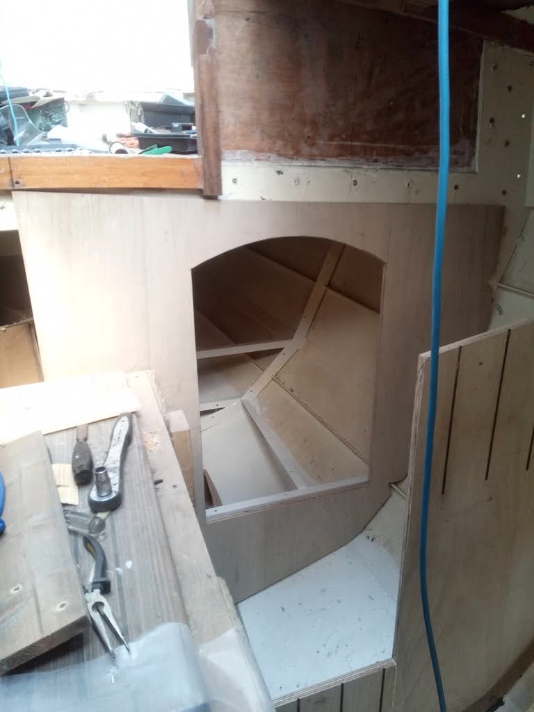
Having secured these pillars, it was back onto cutting more bulkheads. The next to go was the partition at the aft end of the galley, separating it from the battery box and entrance to the space under the cockpit on the port side, which will be the cockpit locker and “technical space”. Before I could template this and cut it out, I had first to establish exactly what the layout of the galley and engine box (at least the port side of it) would be. I had originally intended to have a U-shaped galley and therefore this partition would be at least worktop height right out to the side of the engine box. This would compromise the walk / crawl through access to the technical space by having to step down the side of the companionway which would be very awkward. The U-shaped galley relied on the cooker being fixed athwartships at the forward end, with the sink at the aft end and worktop in between. This would be an ideal layout, and a fixed athwartships cooker has a lot of advantages of a gimballed one on the fore-and-aft leg of the galley. However, I have been getting slightly nervous about this concept as I am really not sure how much the boat will heel, and a fixed cooker could be a bit sketchy if the angle of heel gets too high. I found the arrangement fine on Meander, but I knew she did not heel excessively. I also distrust gimballed cookers as it only needs a misplaced steadying hand to upset the entire contents of a boiling pot. However, there is also a lot to be said for them, properly protected, when cooking at sea when heeled or rolling. By reconfiguring the galley to an L-shape, the sink can be located on the forward leg (sinks are best placed with the drain as close to the centreline as possible, although this assumes they drain straight overboard and not into a tank as mine will), and the cooker on the fore-and-aft leg on its gimbals. Or, I could still install the cooker athwartships if I can establish it will be useable like that, with the sink right aft. After due consideration, I have chosen the L-shaped galley in order to allow easier access through to the technical space – there will be a wide enough gap for stepping up and through between the engine box and galley units. This established, I could now cut the bulkhead and install it.
At some point when routing v-grooves in the bulkheads, I attempted to change the bit in the router which I have had for about 15 years and has done me fine service. It wouldn’t budge – the collet was completely stuck. The only ways I could think of extracting it were destructive and it was whilst attempting to free it that it seized altogether. After dismantling the machine to try to find and resolve the problem, I decided it was probably better to retire it and buy another, so a quick trip to Screwfix was required, and I became the proud owner of a new Trend router.
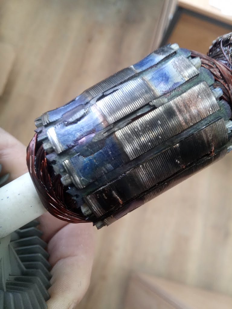
The very next day, I was happily cutting a bulkhead with my trusty circular saw, when it suddenly started smelling very hot, sparking furiously and smoking. Stopping what I was doing, I unplugged the saw and again dismantled it to see what was wrong. What I found was that the contacts on the rotor were completely worn down – the poor saw had lived out its useful life. Once again I got onto the Screwfix website, and became the proud owner of a new, cordless one. Quality definitely matters – having splashed out a bit more I was very impressed with how much cleaner it cuts – requiring far less planing and sanding to clean up the edges. It also has the bonus of sharing the same battery as my cordless drill and cordless grinder.
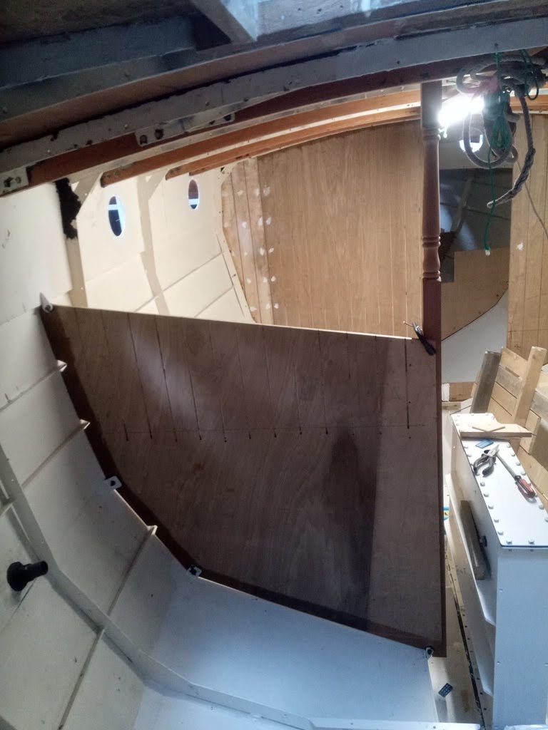
Anyway, back to the bulkheads. The aft galley bulkhead was going to be the last one to install, but whilst considering how to build the rest of the internal furniture, I decided to fit a couple more. Firstly, I decided that the dwarf bulkhead at frame 1 in the forepeak would look a little strange, and it would be difficult to carry the internal lining planks right forward and secure them on the stem. As access is only required to the forepeak in order to step / unstep the foremast, there was no need to keep the space open, and by fully closing it off with a bulkhead (with large body-sized access hatch in it), it would mean that that section would not require lining out – the foam insulation could be left bare and no-one would see it except me. this was pretty quick and easy to template and cut (with my new saw), and I was able to join the top part to the bottom by routing a 4mm groove in the edges for biscuit dowels to create a strong glued joint.
The final bulkhead to fit, which I did in two halves, was at frame 8 at the aft end of the cabin. The port side is full height (which is to main deck, not coachroof height), with a crawl-through doorway for passing through into the technical space / cockpit locker. The starboard side is only full height for 185mm to stbd or the centreline, then drops down to the height of the base of the quarterberth. The two halves are, as with all the bulkheads, bolted through the ring-frame, and also joined at the centreline again with glue and biscuits. It was particularly important with this bulkhead to provide a strong basis for securing the engine box, but also keeping the apertures between the engine compartment and the aft section to a minimum, to attempt to keep engine noise down.

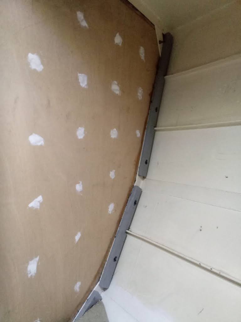
In between fitting these last bulkheads I had already started fitting the timber cleating to all the frames as a base for screwing the lining timber into once the insulation has been sprayed in. It took a while to develop a methodology for producing these efficiently, as each frame requires three sections (for each hull strake), notched for the stringers and (as I established after doing the first few), bevelling to an angle parallel to the hull plating, then for those being fitted to a frame through which a bulkhead has been bolted, drilling and counterboring in order to use the same (deliberately overlength) bolts to secure to the frames. As I have been using cheap softwood (I chose to use treated roof battens, which are a convenient section of 25mm x 50mm, and as they are treated are resistant to rot), each piece is then primed before fitting, and either well-bedded with poo (if fitted to a frame) or glued and screwed (if fitted to a bulkhead). After first tackling those which used bulkhead bolts, and therefore were a bit more time-consuming, as they needed drilling and counterboring on the pillar drill, I established a good routine of measuring, cutting, notching, bevelling, drilling (where required), painting and finally fitting. Those which are fitted to a frame but not using bulkhead bolts could be screwed through the frame with 1″ pan-head screws., whilst those fitted directly to a bulkhead are screwed with 1 1/2″ countersunk screws.
This is quite a dull job, but important to get right now, before insulating. At the end of this leave period, I have completed all the hull framing as far back as frame 8, so as far as the hull is concerned there just remains frame 9 (under the cockpit) and the transom to do. However, the coachroof sides are also going to receive the same spray foam insulation, so I will also need to fit all necessary cleating around the inside of the coachroof, including around the portholes. This job will therefore continue next time I am home!

Also to tackle next leave is the centreboard. I have been humming and ha-ing about whether to spend time cladding the steel plate in ply and fairing it to an aerofoil shape and sheathing in glass and epoxy. I think the benefits will be limited, but it is also a job which, if it proves necessary, can be done at a later date when the boat is finished. This will save some time now, and enable me to install the board this summer before progressing any further with the internal fit-out, but more importantly because the shed will be empty of other boats, so the telehandler crane can get close enough to drop the board through the doghouse aperture. I will then have to sling the board forward into the middle of the saloon and into its slot, having first moved the centreboard case out of the way. I will then be able to attach the carrier to the board, and then sling the case back into position and lower it over the carrier and board, bolting the carrier in place before lowering it all down into position. Before doing all this of course, I will have to paint the carrier and board with several layers of epoxy primer, then a tie coat and some antifouling. All good fun to come…
Phew. I’m exhausted after reading that update. Thanks Chris, it does make interesting reading. Good work.
I’m pretty exhausted after writing it! I really should write updates more often and in smaller chunks, but often too knackered after a day at the yard to sit down and type!