The Great Foremast Project
Having now returned to work after my latest leave, to the slight chaos of a drydocking of SD Kyle of Lochalsh in the delightful surroundings of Greenock, I can update you on my latest progress, which was the single but somewhat daunting project of building a foremast.
Just to remind you, a couple of years ago I procured a ready-made mainmast, which came from a gentleman who was selling the Crabber 30 he had previously converted to junk rig, but was selling with the original gaff cutter rig. He advertised his junk rig on the Junk Rig Association website, and as the mast was extremely close to what I needed, I jumped at the opportunity to save myself a lot of work, and bought it, despite being 40cm shorter than what I needed (I have a plan for this, upon which I shall enlarge in due course, probably this time next year!).
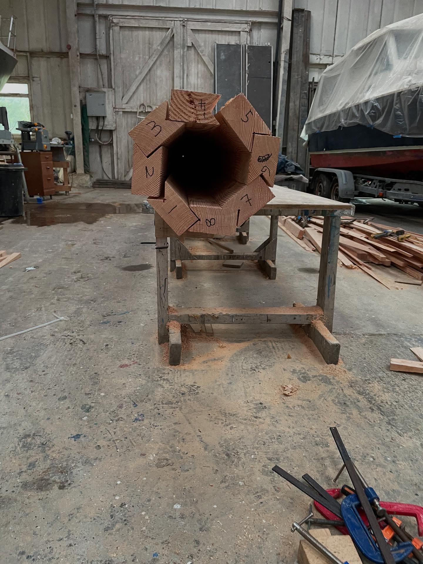
This left me with just one mast to procure, much shorter at 8.9m versus the mainmast’s 12.8m. The original Wylo junk rig plan (the ketch) specified both masts to be solid timber, and indeed that is what the mainmast is made from. However, with a shoal-drafted centreboarder I am conscious of topweight, but even more the effect on the pitching motion that having a heavy lump of timber so far forward in the boat would have. Therefore, I had long ago resolved to build the foremast as lightly as I could without sacrificing strength. Having ruled out an aluminium lamp-post (expensive and more difficult to get hold of than it used to be, since the supplier refused to supply posts destined to be boat masts), and steel masts custom-made but by a lamp-post manufacturer (heavy and expensive), I decided the only way to go was to build a hollow wooden mast. Of all the methods that can be used, the most attractive to me was the birdsmouth method, whereby 8 wooden staves are machined to have a 90-degree “birdsmouth” recess in one edge, and the other edge is cut to a taper. My design for this spar was taken from the Junk Rig Handbook with regards to scantlings (since deemed by those in the know to be about 20% over-engineered), so it has the same diameters as a solid spar would have. The dimensions for the staves were derived from a couple of websites – one article and associated calculator which helped me determine the thickness of the mast walls which was required to produce sufficient strength for an unstayed mast; the other, the Birdsmouth Calculator published on the Duckworks website (now unfortunately being run down by the new owners of the Duckworks business), subsequently gave me the width of the staves required to achieve the diameters at the partners (where the mast goes through the deck – necessarily the strongest part) and at the masthead. Having established these dimensions, I could order some Douglas Fir timber to the required sizes (allowing for squaring and planing), and for this I went to Pol at Black Dog Milling, from whom I had coincidentally bought my mainmast. Once I had established when exactly I intended to build the mast, I could put in an order to be delivered in time for this, allowing for some seasoning / drying, so the timber would have an appropriately low moisture content to be stable enough to build a mast. This timber was locally cut in the estate surrounding Pol’s sawmill at Forteviot in Perthshire.
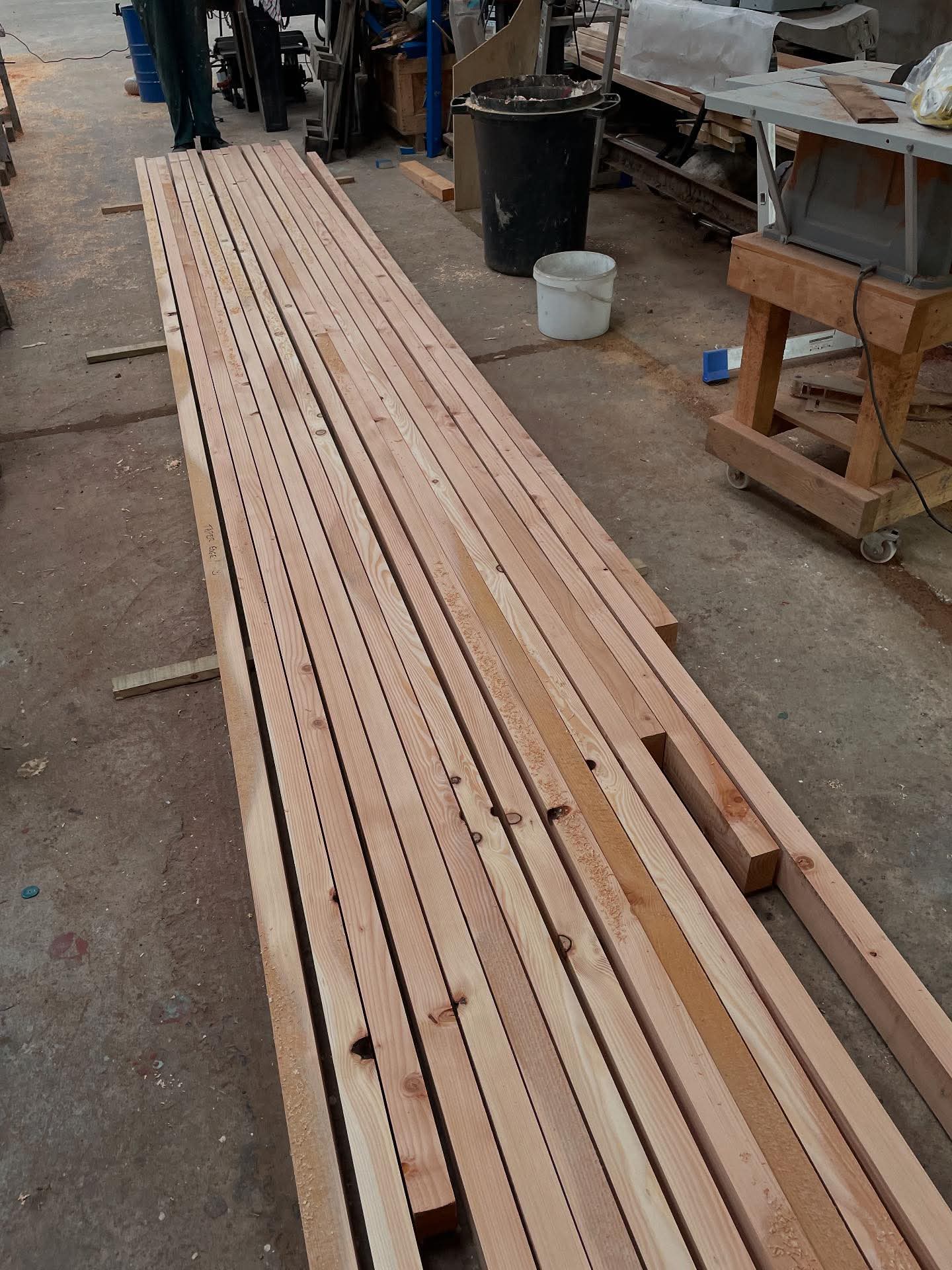
I spent the first week of my leave doing another stint on VIC 32, which was at relatively short notice, and on my way home from Crinan at the end of the week, I had a call from Pol saying he was at Kilmelford with my timber, so I was able to stop off and help him unload his trailer. This left me with a pile of sawn and slightly wiggly planks, so my first task after getting home to do some laundry and recover would be to plane and square all these planks to a uniform 50mm x 98mm section, which was the maximum size for the staves.
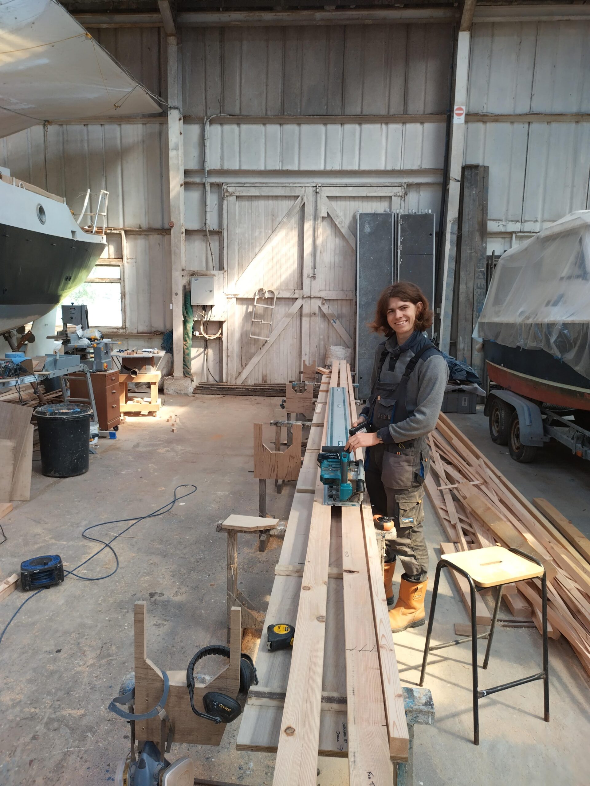
I was hugely fortunate to have been able to recruit some assistance for the first stages of building the mast – in retrospect if I had not had this lucky break, I would not have been able to achieve what I did in the short time available. After mentioning my plan to build a mast in an unrelated message, a young chap I had met on Pelican in 2020 expressed a mild interest in the project, and so I followed up and suggested he might like to join me if he was free. Much to my surprise and good fortune, Louis was able to rearrange his summer holidays (as a student, quite generous ones), and booked himself to come up to Argyll from his home in France for a week. He arrived on the Sunday afternoon, so work in earnest started on Monday morning at 0830!
It was very much a case of the blind-ish leading the blind in this partnership, as I had never made a mast more than maybe 3 metres long and about 75mm diameter, and it was a solid spar, not glued up as in this case. During the following stages we had to very much develop each process as we went, although with my reading and setting-up, I had already given them a good deal of thought and had some ideas.
Stage 1: Planing and Squaring
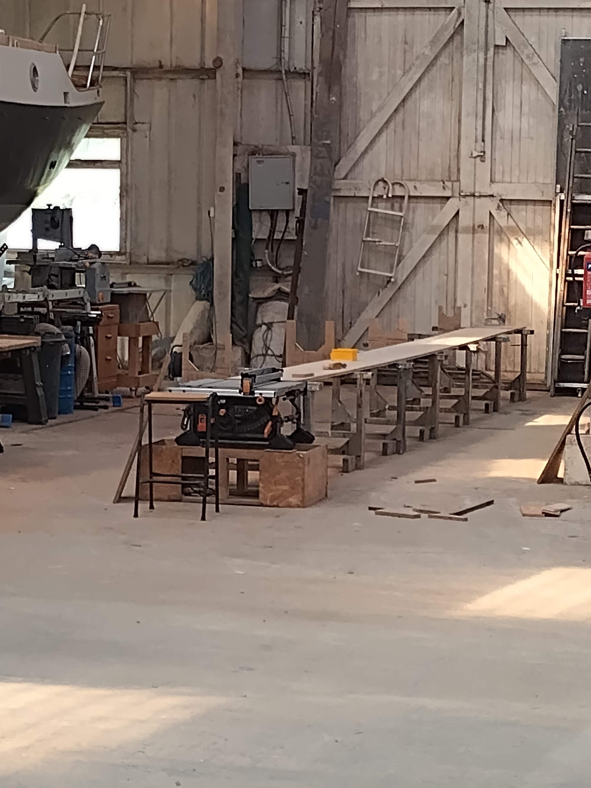
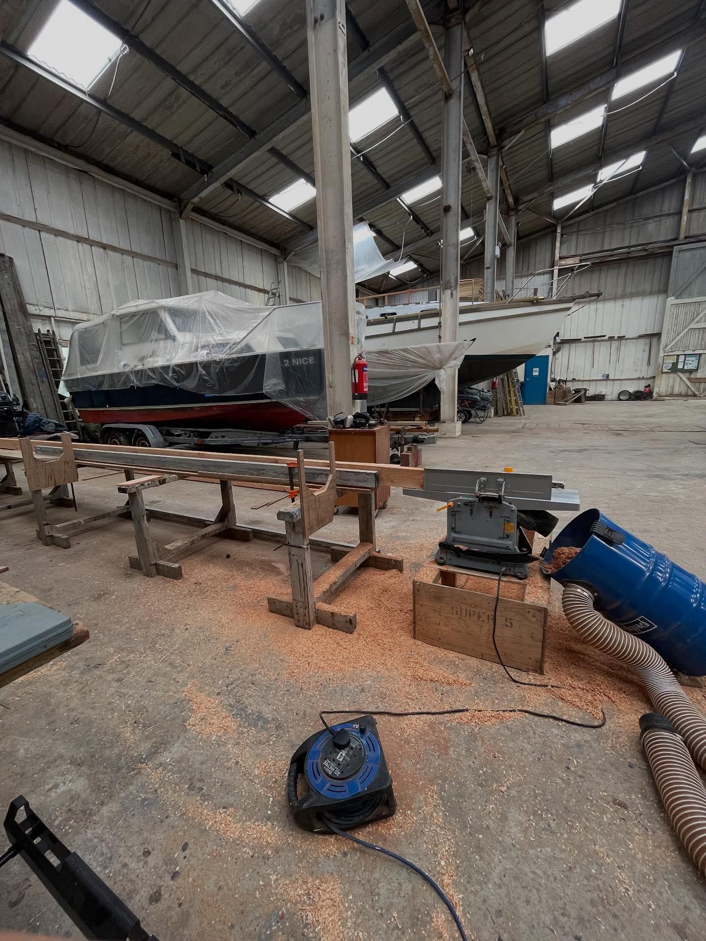
As mentioned above, the first stage of the procedure was to square and plane smooth all the planks to a uniform size. To do this I set up my planer / thicknesser (basic Titan cheapie from Screwfix) level with the 8m long bench I had previously set up in the empty bay next to the boat in the shed. With this we planed one wide side of each plank smooth, which required several passes over the planer table. Each plank being 6m in length, this was quite a strenuous task, as there is quite a lot of friction between plank and table, particularly when the plank is still rough sawn. Both of us puffed and panted and got all 20 planks planed on one side, then had to repeat the process, this time to square and plane one narrow edge, so I (at the planer) had to keep the plank tight up to the fence as we pushed it through, to ensure the edge ended up square to the already-planed face. Louis was pushing and pulling, to help the plank feed over the table. Once all 20 had been processed this far, the next stage commenced. The planer / thicknesser was reconfigured to thicknesser mode, and stood on its little chest in the middle of the shed, with a roller stand either side to attempt to keep the planks horizontal as we fed them through. We then fed each plank through to thickness them to a uniform 50mm thick. It was during this process that the machine started to struggle, sometimes ripping up the face of the timber more than it should ( a good sign that the blades are getting dull), and occasionally stopping feeding the timber through altogether. I took a 10 minute break to jump on the Screwfix website to get some new blades, only to find that they were not in stock and we’d have to wait 2 days until they were in store ready to pick up. I therefore decided to have a go at honing them myself on my small sharpening stone. This took half an hour or so, and after reinserting the blades there was a definite improvement in performance. We cracked on and planed a few more, but the planer then started making more and more noises, until at the end of one plank there was a definite change of note and it suddenly sounded like a bag of spanners, and this was accompanied by a very hot smell. After a bit of investigation, I came to the conclusion that the cutter drum bearings had probably given up the ghost, and there ended the useful life of that machine (you can’t generally get spares for Titan tools, as I guess they are considered to be disposable). The only option I had open to keep the job on schedule was to take a trip into Oban to get an entire new machine, which fortunately was in stock in Screwfix.
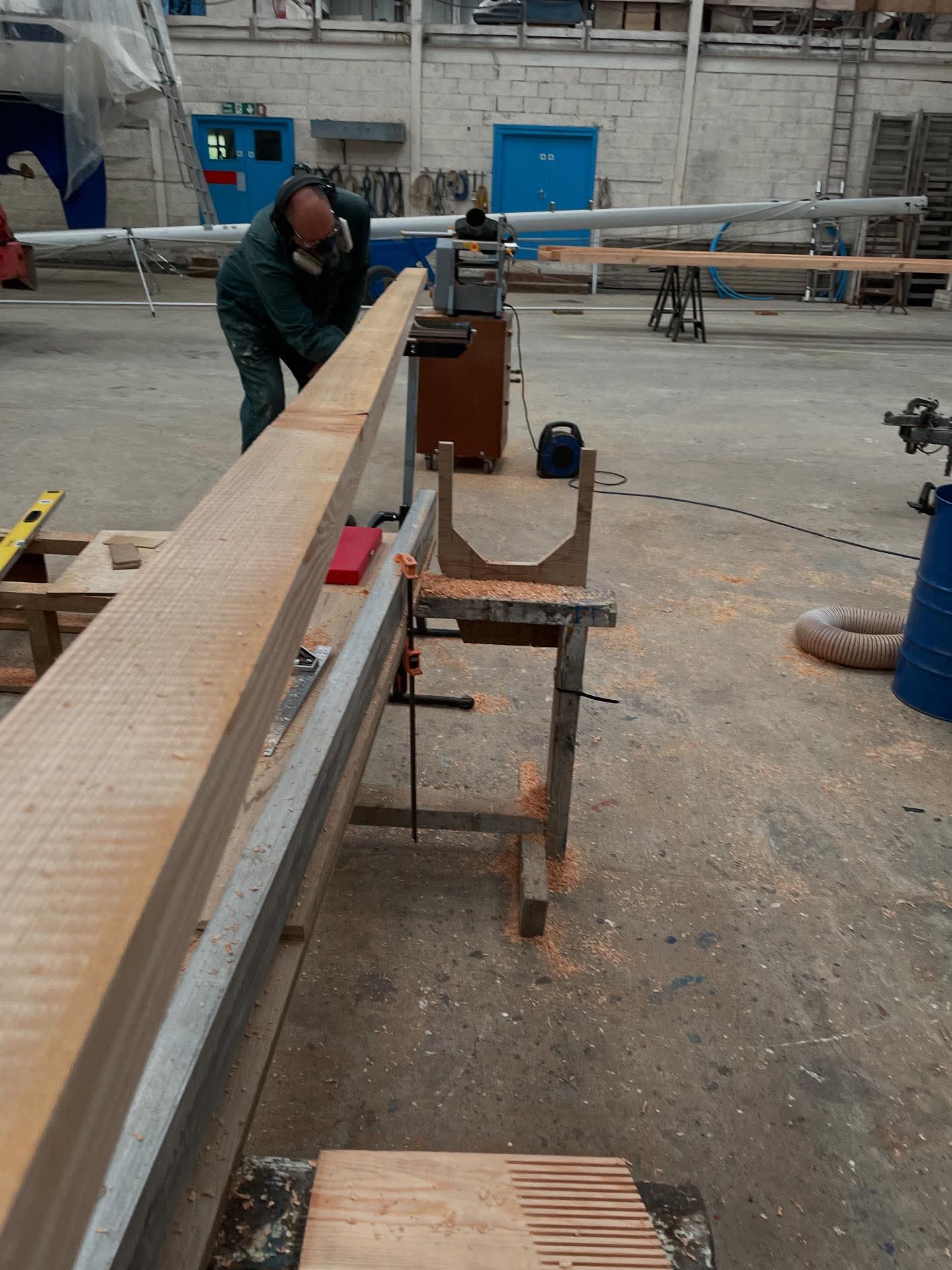
An hour or so later, we had the new machine, and once it was assembled and set up, we could continue with the project… and what a difference! The new machine with its fresh blades cut through the timber like butter, and we made short work of the remaining planks. Finally, we ran them all through on their edges, and got the final edge planed and the width to a uniform 98mm. This was the maximum width which would produce final diameter required of 230mm at the partners (where the mast passes through the foredeck) once the mast was assembled.
Stage 2: Scarphing the staves to length
As already mentioned, the planks which Pol delivered were 6m in length, but the mast is 8.9m from truck to step. Therefore the next job was to join many shorter pieces of wood to make up 8 staves of 8.9m (or a tiny bit more to allow for idiocy). Obviously in a mast, the key is that any joints should be strong and thereby not introduce any weaknesses into the column. There are many different schools of thought as to what length a scarph should be: some say 6:1, some 9:1 and some 12:1, and it does depend to a certain extent on the type of timber. As Douglas Fir is a softwood, a longer scarph is required, and my reading pointed towards a 12:1 ratio. With a 50mm plank thickness, this makes for a 600mm long joint, and during one of my weekends on my previous stint at work I had constructed a scarphing jig to use with my big router, to ensure nice uniform smooth glueing surfaces.
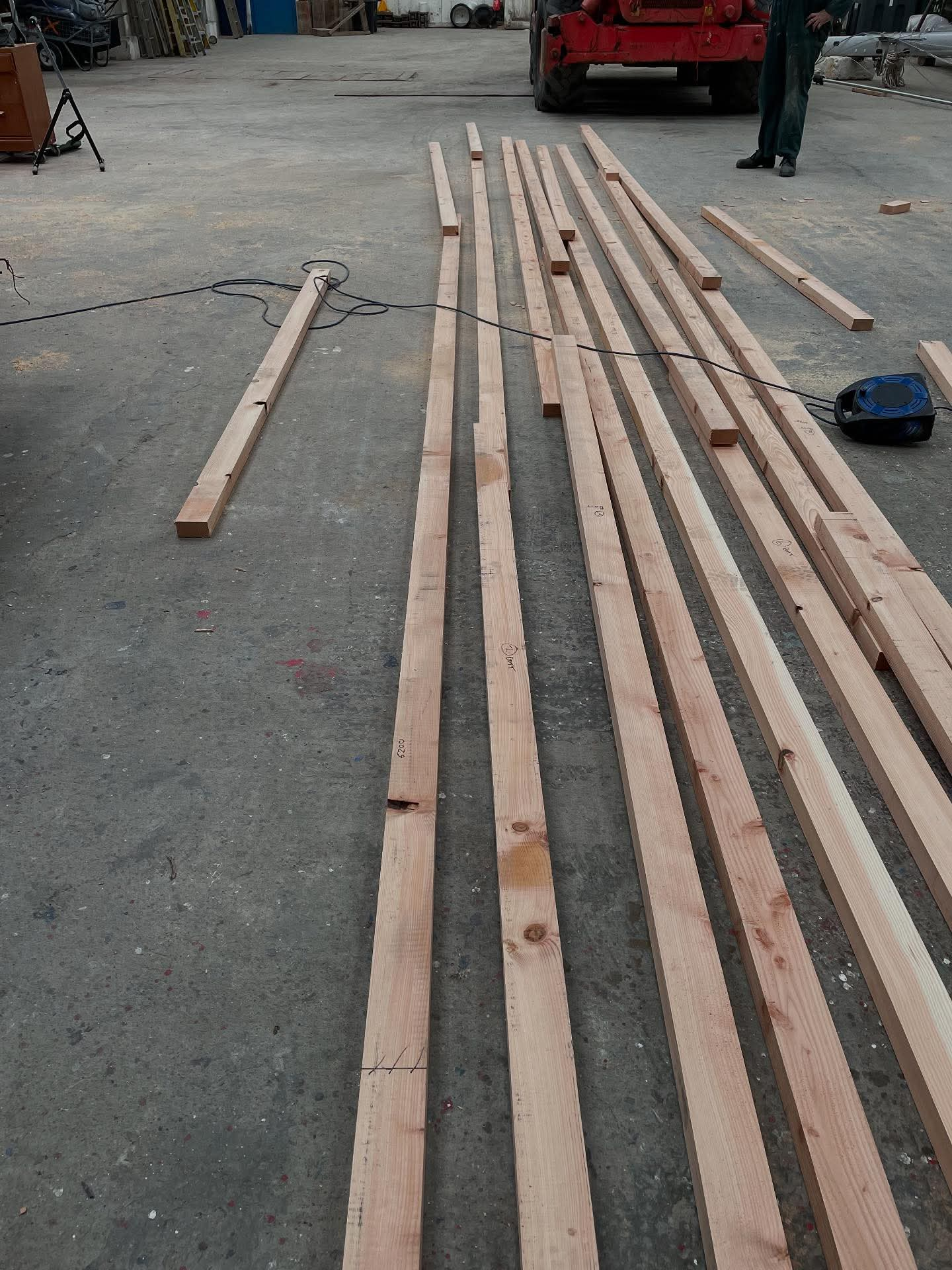
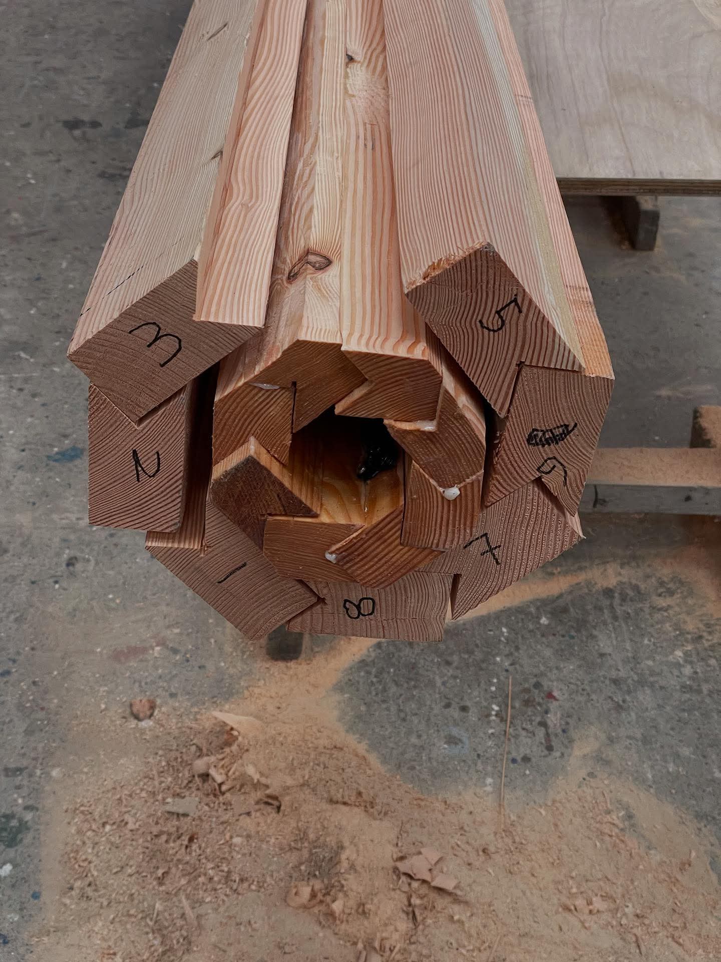
It is also important to ensure that scarphs do not coincide anywhere in adjacent planks; to this end I had already drawn a plan of how the scarphs would be arranged in each numbered stave, and so Louis and I set these out on the shed floor, deciding which bits of timber would go where, and if possible discarding the sections of timber which had checks (splits / cracks) in them, or any bad knots. Once they get to a certain stage of their lives, knots create a weak spot in the plank, and in the worst cases the knot had already popped out of the “parent” plank during the planing process. Other knots we would be able to eliminate by ensuring they were cut off during the tapering process, or if they coincided with the birdsmouth (in a couple of cases), the knot would be popped out and the hole filled with thickened epoxy during glueing. Eventually we ended up with planks arranged and cut so that once scarphed they would end up at least 8.9m long; we would have six staves each with one scarph in them, and two which would have two scarphs, making a total of ten joints, each requiring two faces to be cut and smoothed.
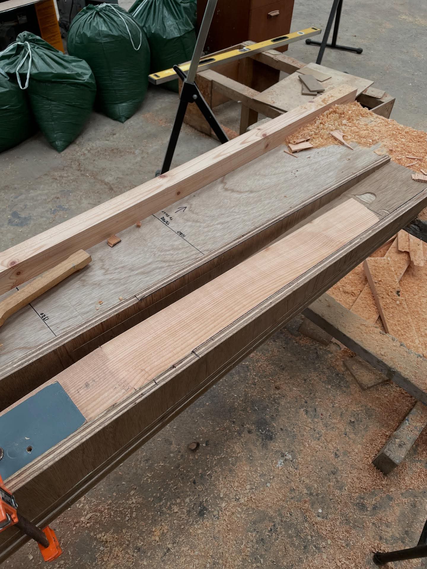
I opted to use my circular saw to cut the initial slope into the end of the plank. At 50mm thick, this is on the hairy edge of the limit for my battery saw, and a fully charged battery, once I’d worked out the technique, would do about two and a half of them. Therefore I had to have a constant rotation of batteries through my (single) charger, and follow the routine of cut – smooth – cut – smooth on each successive slope to allow time for batteries to charge (fortunately the charger is pretty quick). The router scarph jig made smoothing the glueing surfaces quite straightforward, as long as the plank was well-clamped, square and flat in the jig. Even an accumulation of sawdust under the plank would introduce an unwelcome inaccuracy.
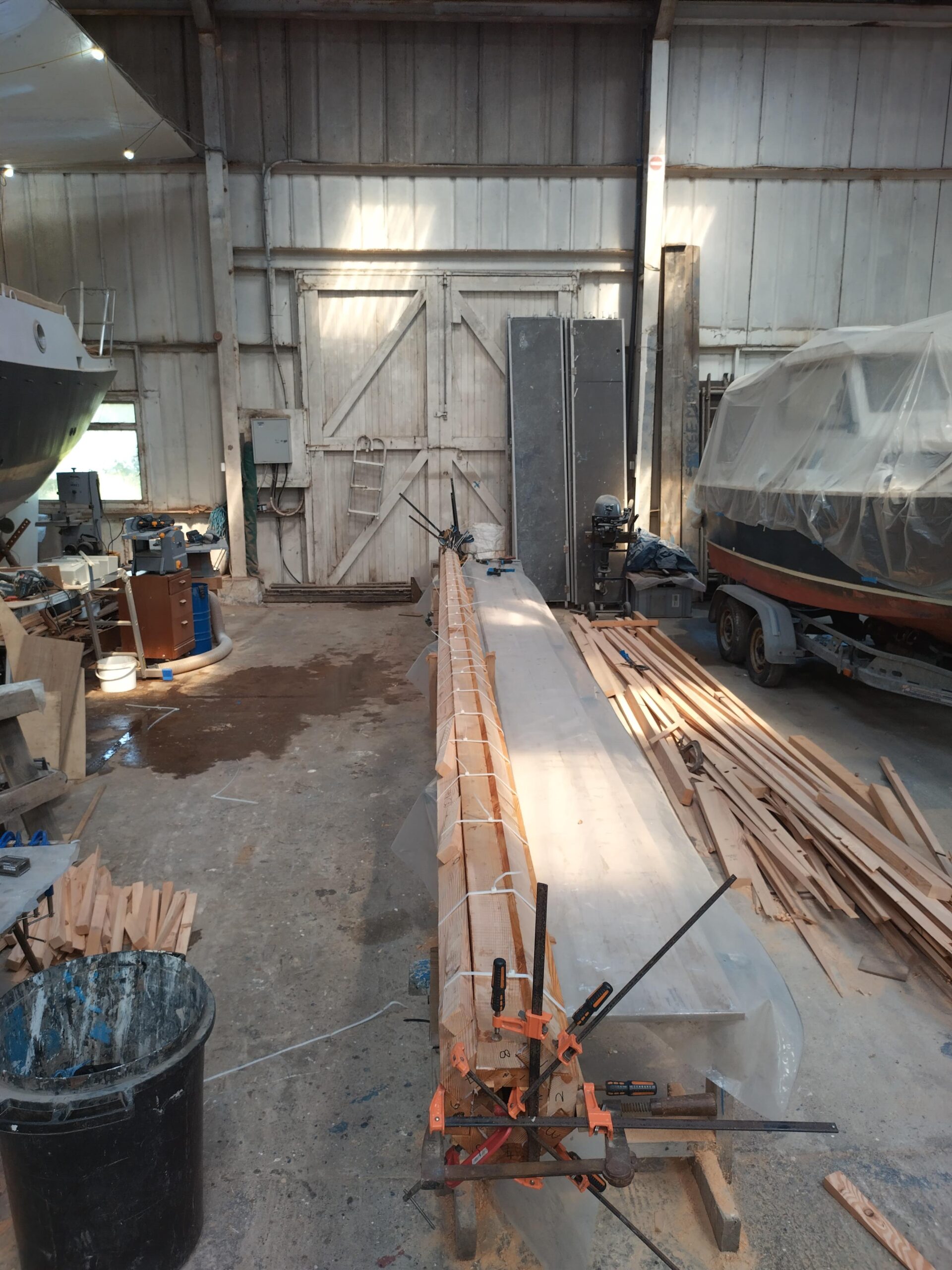
As it was already Thursday by this stage, in order to speed the process up, once we had a couple of planks with their scarphs cut, we glued them up straight away whilst we cut the other planks. This meant that we should be able to get through all the glueing by Saturday, which we would then spend sawing the staves ready for the big glue-up. The aim was to glue two staves at the same time, and we set up a straight edge on each side of the long bench to clamp these against. To help with this, my neighbour in the shed, Mike, who is a boatbuilder and engineer, had lent me some long aluminium straight edges and a laser guide to help set these up. Before doing any glueing I had to go foraging in the shed for numerous clamps, as I have a limited number. We managed to scrape enough together to be able to glue up one single-scarph plank and one double-scarph plank at the same time, but it was a push to find this many! once the bench was covered with plastic, we started glueing. The process was to get the planks set up on the bench in the right order, then apply thickened epoxy to both glueing faces, in quite generous quantities, before lining up and clamping. I cannot emphasise enough how much I appreciate epoxy as a glue and a building material. It is a comfort to know that when used properly it can compensate for my lack of accuracy as a woodworker, and create joints which are stronger than the wood itself. These properties would definitely come in even more handy later in the process!
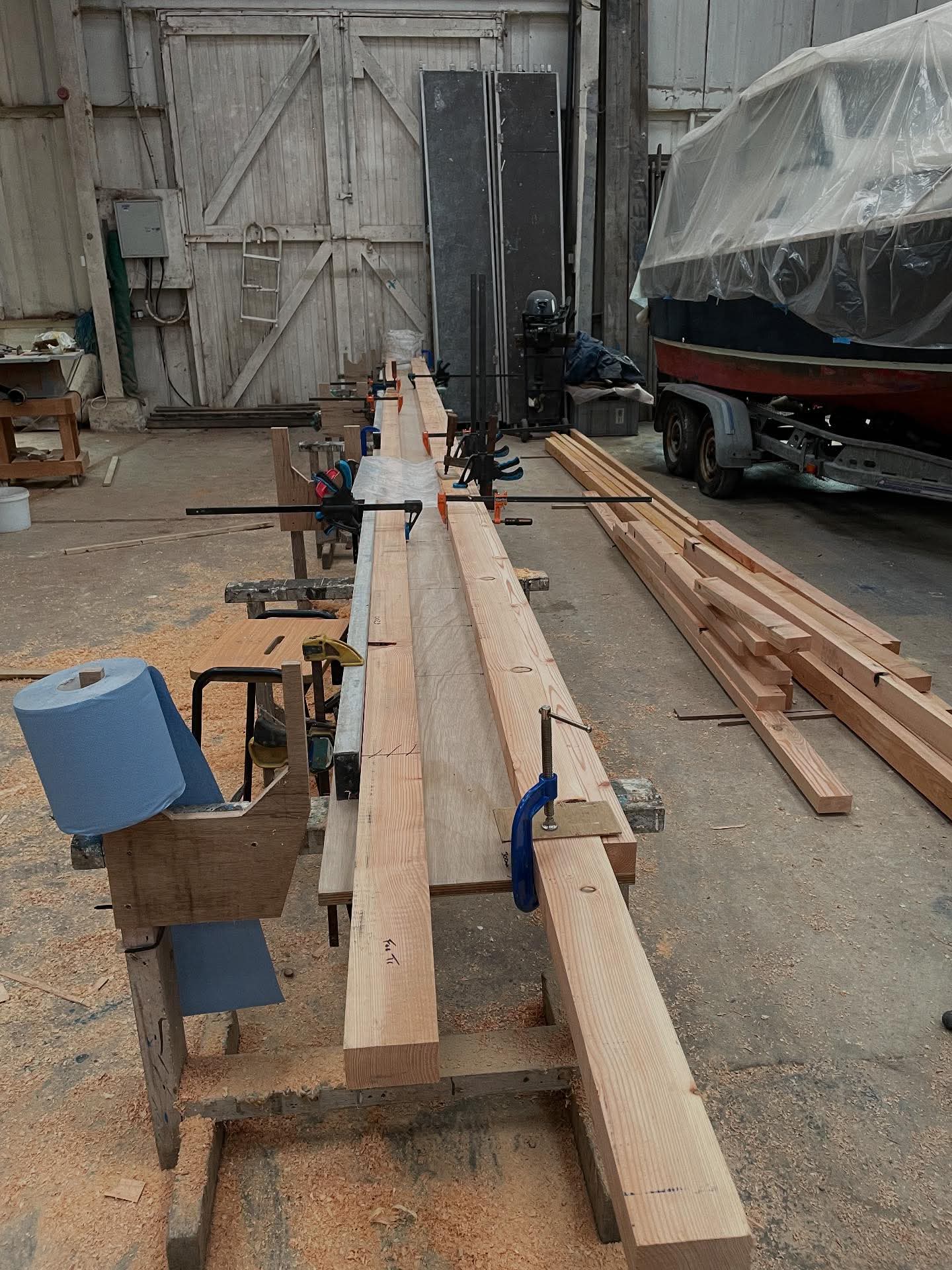
Once the first two staves were glueing, we continued cutting the remaining scarphs in the other planks, and left the epoxy to cure overnight, with another two staves waiting to go first thing the next morning. This way we managed to glue four staves in total the next day, as if we glued one pair up in the morning, it would be sufficiently cured to move them off the bench by mid-afternoon, allowing us to glue a second pair before finishing for the day.
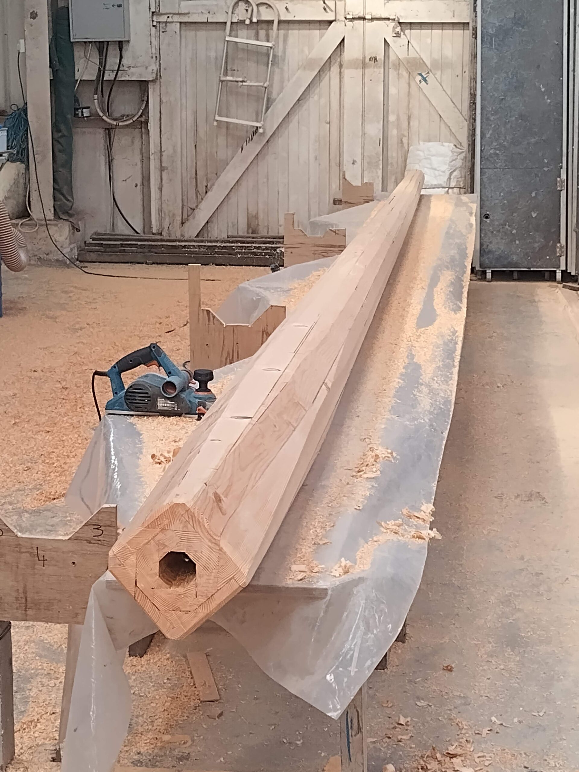
Stage 3: The Plug
The Friday morning saw us glueing up the final pair of staves. Whilst the glueing staves were curing, there was still plenty to do. Louis was mostly busy with cleaning up the cured scarph joints, removing the excess glue with a mixture of planes, surforms and sanding. Meanwhile I needed to think about building the plug, which would reinforce the bottom two metres of the mast, where the stresses are greatest just around the partners. I had decided to make this a dry-run for glueing up the mast, so made it using the same birdsmouth process. With some sketches, some trigonometry and some head-scratching, assisted by the online Birdsmouth Calculator, I was able to determine the width of the staves I would require to make an octagonal-section plug to match the inside dimensions of the glued-up mast (I hoped). Whilst Louis was busy cleaning up scarphs, I was able to cut, square, plane and cut to width the 2.1m lengths of timber required to make the plug. In order not to produce any point stresses on the inside of the mast, the staves for the plug would have to taper to a point at the upper end, reducing the thickness of the mast walls gradually. I cut these tapers first, then ran each one twice over the table saw, set to exactly 45 degrees and the correct depth to create the birdsmouth in one edge. With Louis’ help, I then coated the inside and face and inside of the birdsmouths with unthickened epoxy resin. Whilst this was starting to cure, I had time to fit the cable conduit to the inside face of one stave, as this would not be possible once the plug was fully glued up. It’s worth saying here that in a perfect world, with more time and if Louis was available for an extra couple of days, it would have been possible to glue up both the plug and the mast in two halves first (by assembling with two opposite joints unglued and lined with parcel tape) – that way the internal coating and any work to the inside such as fixing the conduit or just cables inside the mast could be achieved by doing the first glue-up to create two halves of the plug / spar, separating them, doing the necessary inside, then glueing the two halves together. However, this not being the case, the conduit had to be fitted as we progressed, and I was left with either an annoying coil or a 7m snake to contend with whilst manoeuvring the glued-up plug (more on this in due course).
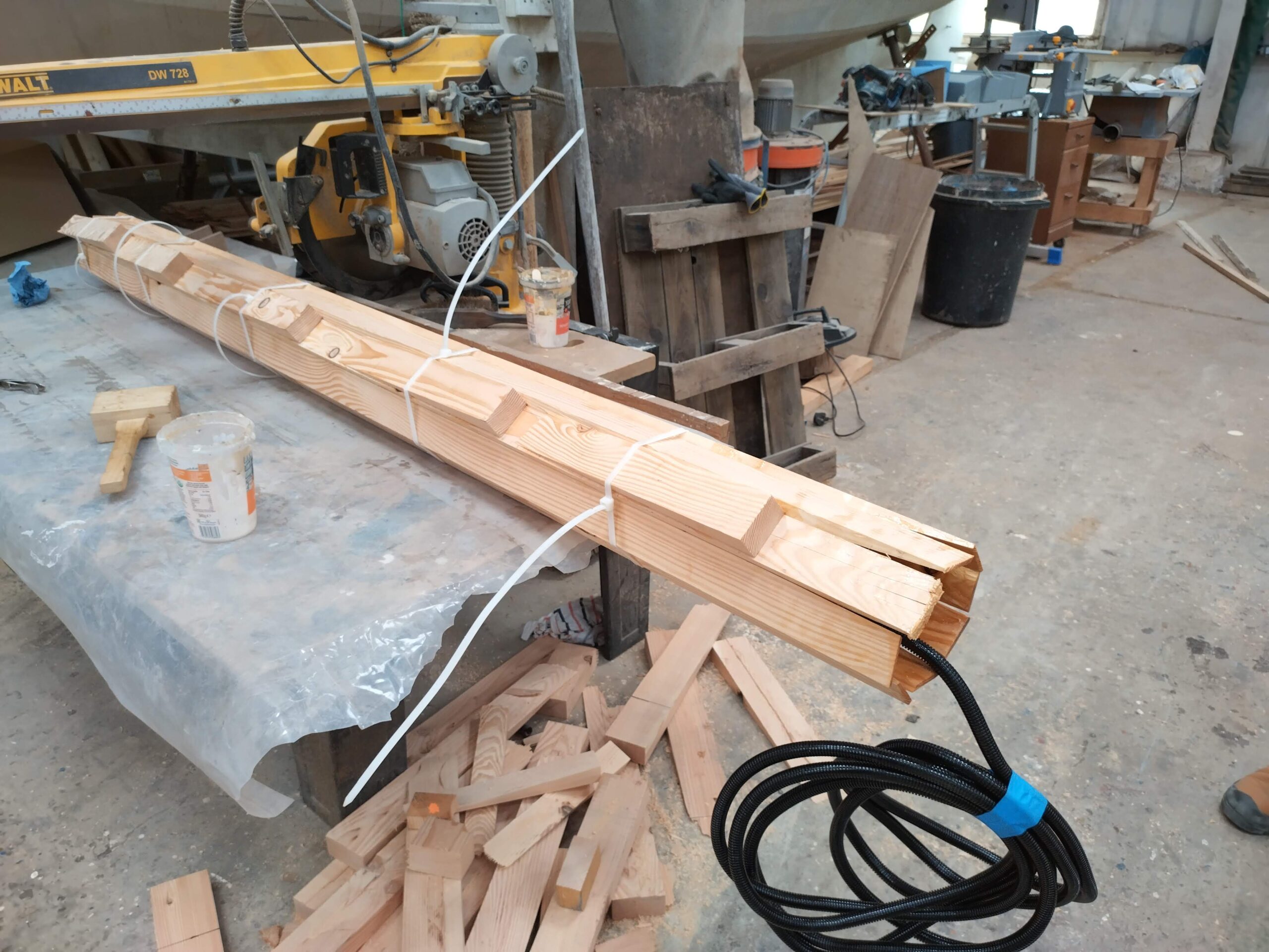
Once we’d got all the staves nice and sticky, and the resin had got to the tacky stage, we could then progress to the next stage, and glue the plug up fully. More thickened resin was produced, and having slathered the inside of each birdsmouth with a reasonable amount of goo, the staves were assembled in numerical order, and clamped together with some of the largest cable ties I have ever seen. These were further tightened using wedges, and the glue left to cure overnight.
Stage 4: Sawing the Staves and Planing the Plug (and an annoying mishap).
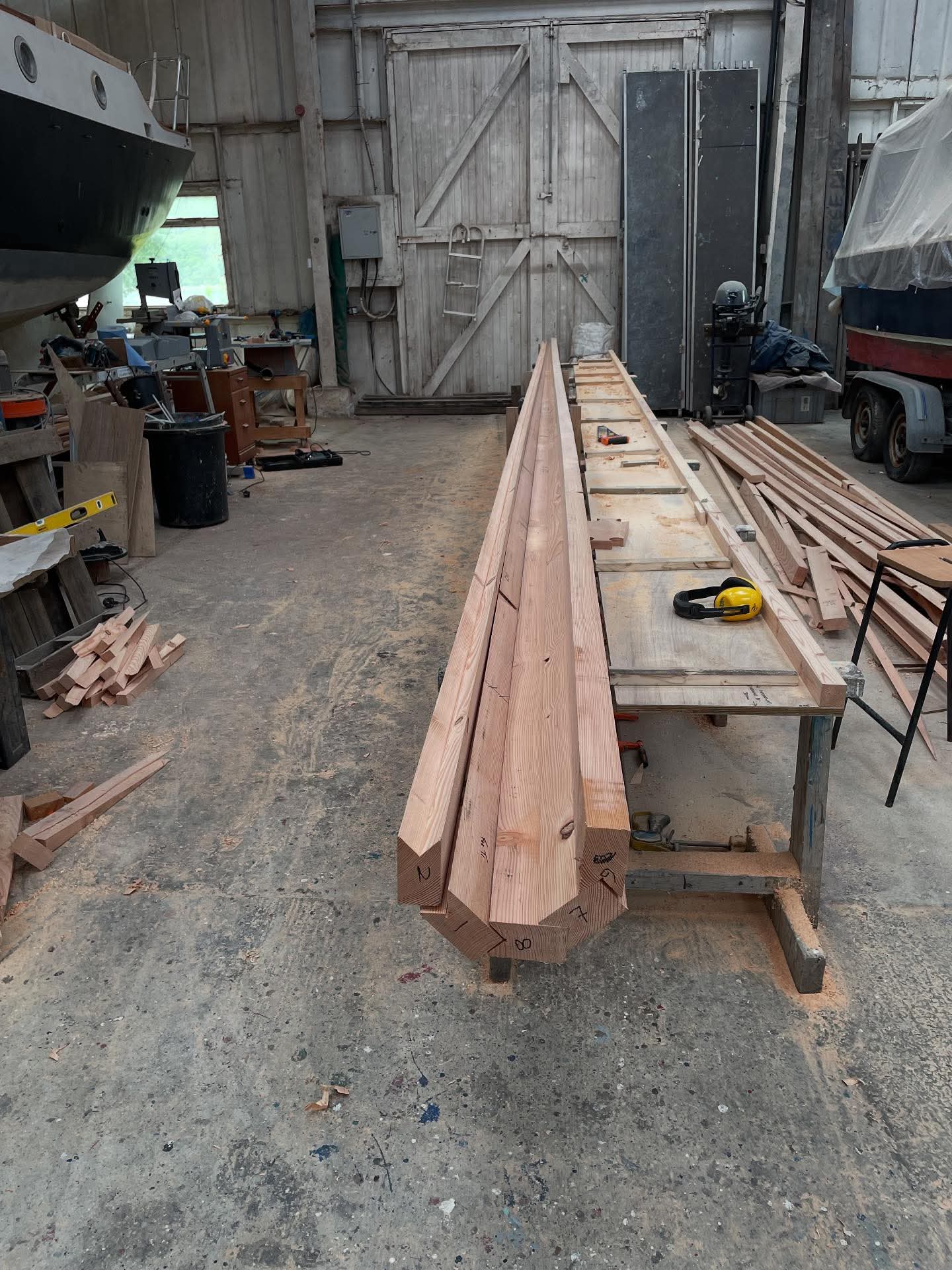
Saturday dawned, and Louis and I had a busy day ahead of us, if we were to achieve the goal of glueing the mast up on the Sunday. We had our 8 staves planed, scarphed up, and then cut approximately to length. We actually ended up with two staves slightly short at 8.85m, which was mildly irritating but not earth-shattering – I could live with a mast only 5 cm short. Next we had to cut the birdsmouths and then finally taper each stave.
For cutting the birdsmouths, I set my table saw up at the end of the long bench, and placed short lengths of copper pipe at regular intervals along the bench to use as rollers to reduce friction. My two roller stands were set up at the other end of the table saw at suitable intervals, to take the weight of the staves as they came off the saw. The blade was set at 45 degrees again, and at a depth of cut to make sure the two diagonal kerfs would meet at their apex. The fence was set up very close to the blade to ensure the cut made a sharp edge with the wide face of the stave. We then ran each stave on edge twice over the saw – once in each direction – until there was a 90 degree birdsmouth in the edge of each stave. This is where accuracy counted, and unfortunately I could not claim 100% accurate cuts, as keeping the stave up to the fence as we moved it through the saw was quite difficult, but I feel we did a reasonable job of it.
To taper the stave we first set up each stave on the long bench, tight up to the straight edge, with a measured mark at the point where the taper was to start alongside a matching mark on the bench. We then used a chalk line to mark the line of the taper so that each stave was reduced to a width of 40mm at the masthead. Once the taper was marked, the stave was supported on scrap wood to raise it off the bench (I intend to reuse the 18mm plywood I made the bench top from as sole boards in the boat in due course, so didn’t want to damage it with the saw), and pulled it away from the straight edge far enough to allow the saw in to start the cut at the bottom end. I had arranged with the yard to borrow their Makita rail saw, which is 36V rather than my 18V, and has a longer rail. Using a second stave on the bench alongside the one to be cut, the rail was well-supported to ensure a square cut, the rail was set up along the chalk line and we started each taper from the bottom. The first cut took a while to start – the saw seemed to want to veer off course and much smoke was produced, which pointed to a blunt blade. Fortunately Dave had a couple of spare blades in the box with the saw, so once we changed blade things went much more smoothly. Halfway along each cut we’d have to shuffle the rail along so we could complete the cut, and again I had to master the trick of ensuring it lined up with the first half of the cut to get a straight edge.
Once we had the knack, the process ended up being far quicker than we expected, and we soon had 8 tapered staves, albeit not before having to change the blade a second time after the same symptoms appeared on the penultimate taper.
After finishing the tapers we did a dry fit of all the staves together, and then I started planing the plug down to fit the inside of the mast. The way the staves glue together, the first stage to planing is to get rid of the “ear” on each joint – a triangular section due to the thickness of the stave being greater than one side of the birdsmouth. This creates an octagonal section, which is what we required for the plug. It was during this process I realised that my venerable electric hand planer may not be entirely up to scratch when it came to accuracy. It turned out it had a nasty habit of taking great gouges out of the material, even when planing depth was supposedly set to zero. I resolved to purchase a better one for rounding the mast itself; in the meantime I would have to take great care whilst planing the plug to shape / size. It seemed that the measurements I used for the staves produced a larger plug than would actually fit in the mast as cut, so I had a very frustrating time planing the faces of the plug whilst trying to keep them all at 45 degrees to each other and of a uniform width, with a dodgy monster of a plane. Once I got the plug nearly right, I decided to try passing it through the thicknesser to finish the final adjustments. Whilst moving the planer / thicknesser into a suitable position to do this, mild disaster struck. One of the castors of the chest on which the machine sits got caught in a slight irregularity in the concrete floor, and “tripped” the chest, flinging the machine off the top. This then landed upside-down on the floor, and in doing so, being a weighty thing, the planer surface was deformed. Bear in mind that I’d only bought this machine 3 days beforehand, and you can imagine how annoyed I was with myself! As I still have its predecessor, I hope in the near future to be able to cannibalise the old one to make a good machine out of two damaged ones, so all is not lost, but my God how annoying that was!
Stage 5: Glue-up day!
Sunday had finally arrived: Louis’ last day with me and my deadline for glueing the mast up into a monolithic spar. For this process, the more manpower one has, the better, so I had previously asked Mike if he would mind sparing a few hours to help with the glue-up, and he willingly agreed. He was not due to turn up until about 1030, so we spent the first couple of hours of the day setting up. I gave the plug one final (gentle) plane and dry fit, and then we set up an epoxy station on the adjacent workbench, covered with plastic sheeting and neatly laid out with everything we might need for mixing resin and glue. I had realised that I might run slightly short of the Colloidal Silica powder used to thicken the epoxy resin into a glue, so Mike kindly donated me an extra pack of this to keep in reserve for as long as I needed (I only ended up using a few scoops of it during the post glue-up stages).
By the time Mike arrived, we had everything set up, with the staves laid out on horses ready to slather with resin and glue. I held a quick briefing on the process, and then we got going, first coating the glueing surfaces and inside faces of each stave with raw resin, as well as the outside surfaces of the plug. There followed a short interlude whilst we waited for the resin to go tacky, then once it was we then brushed glue into the birdsmouths, and a thicker mix spread on the outside of the plug. As all the staves have to glue together simultaneously, all of them had to be spread with glue before assembly, so there was a reasonable sense of urgency to work and get it assembled before the glue started curing. The first three staves were laid into the jig, and then the plug was laid in its position in the bottom of the mast. The conduit then had to be laid out along the length of stave 1 (the bottom one), and clipped in place. The remaining staves could then be slid into position and the final one slotted into place.
At this stage the staves were still all fairly loosely meshing together, so we then gradually applied pressure with the big cable ties at regular intervals, as well as using a web of clamps to ensure the bottom ends of the staves and the plug were all mating together nicely. We ended up with a cable tie every 20-30cm, some wedged for extra tension if deemed necessary. After a final tweak to each cable tie, there was little more we could do except leave the glue to cure. We knocked off at about 1530 and went home to clean up for the pub supper I had booked for Louis’ last evening.
…
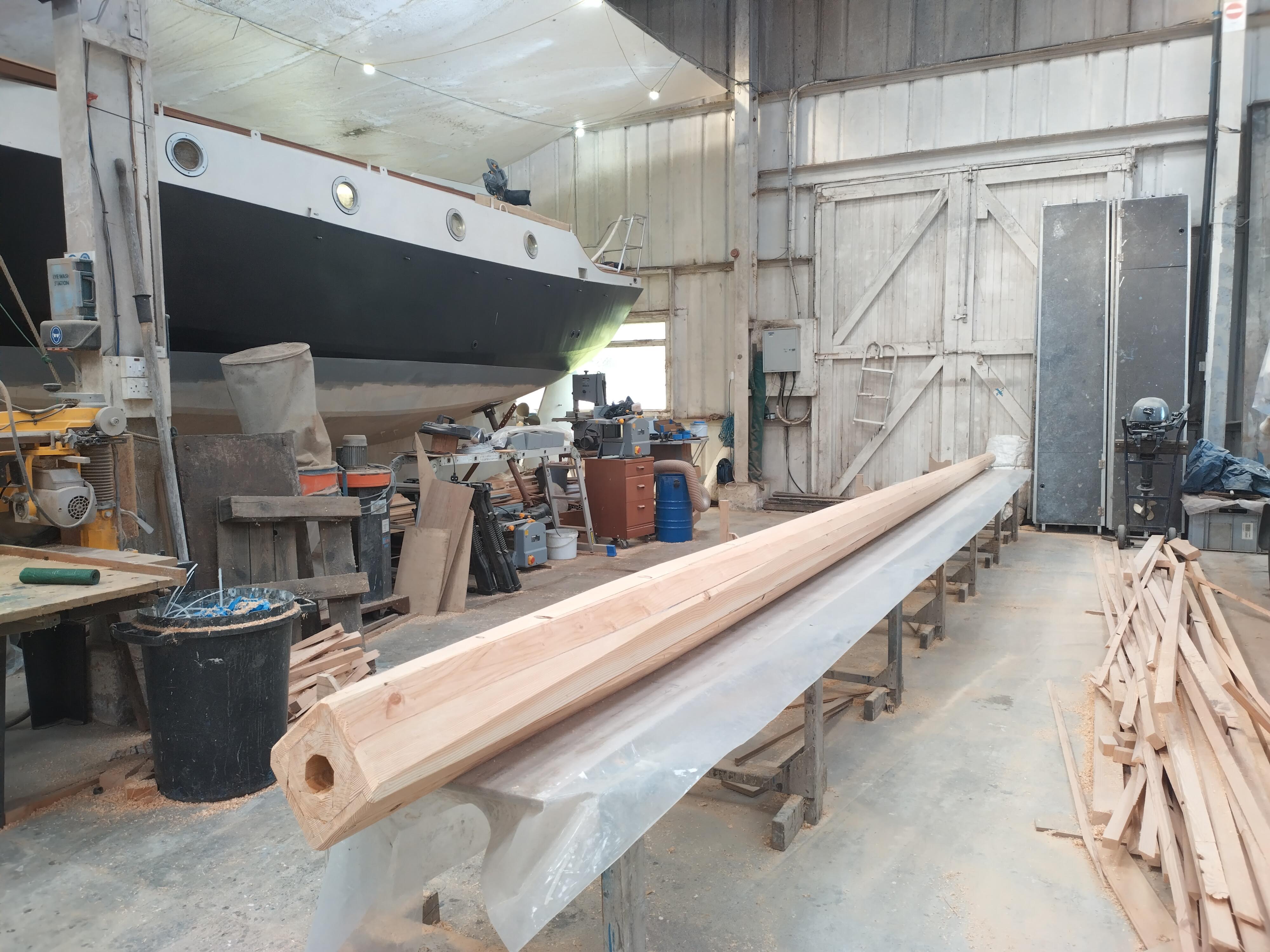
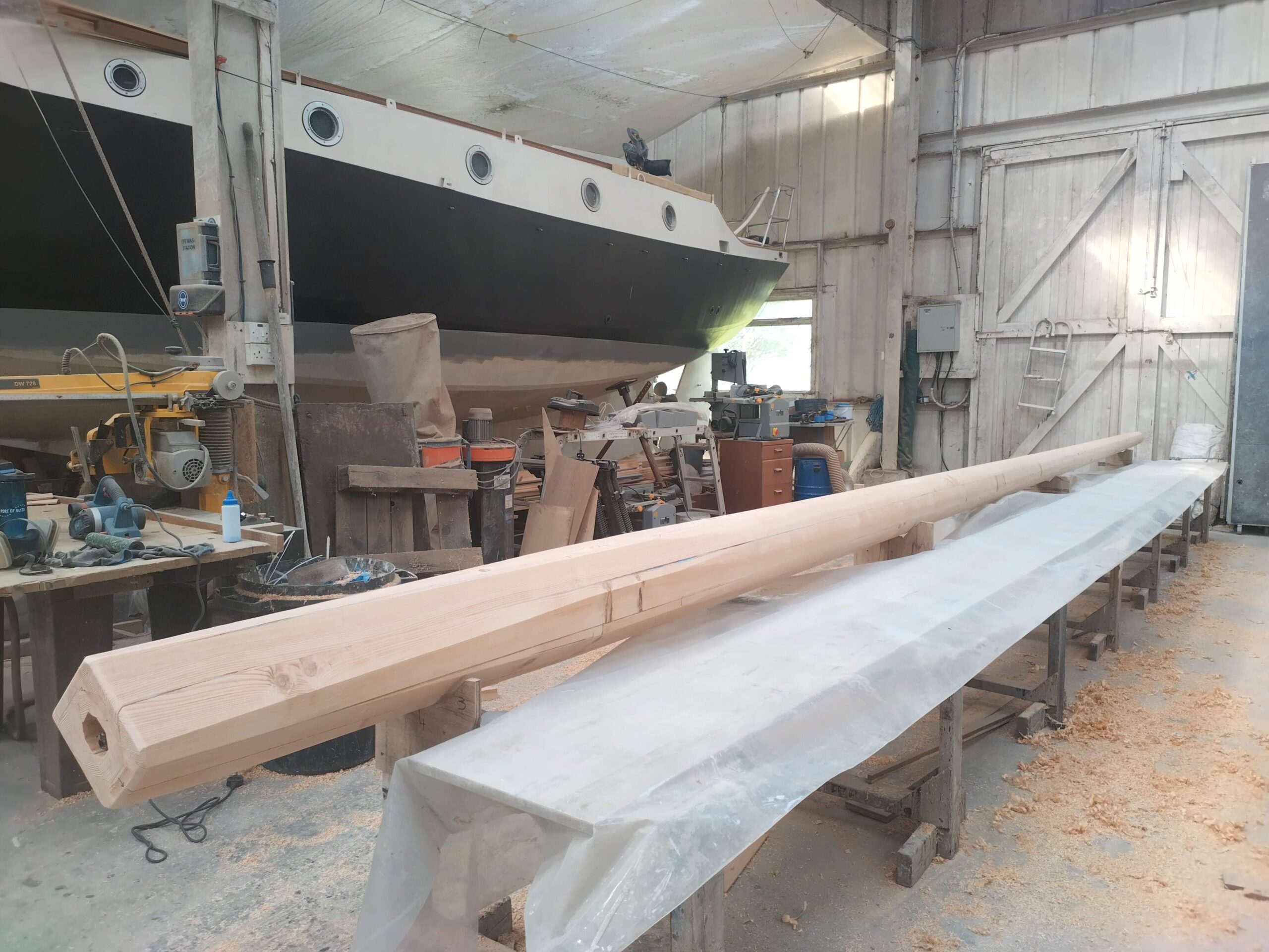
Stage 6: Planing and Rounding
After a busy week with Louis, we’d now got the mast to a stage where I could labour on my own and get the mast to a stage where it could be moved about the shed if required by the yard, and eventually (in Autumn) taken out to the undercover mast store before the shed fills up with boats once again.
Monday I took fairly easily: the first job of the day was to take Louis into Oban to catch his bus to Glasgow and onwards back home to France. It was a slightly precarious drive, as it was the day that storm Floris decided to strike. Oban didn’t get the worst of it – further north on the West Coast (including Kyle) was hit harder, and there were multiple power cuts and tree failures up that way.
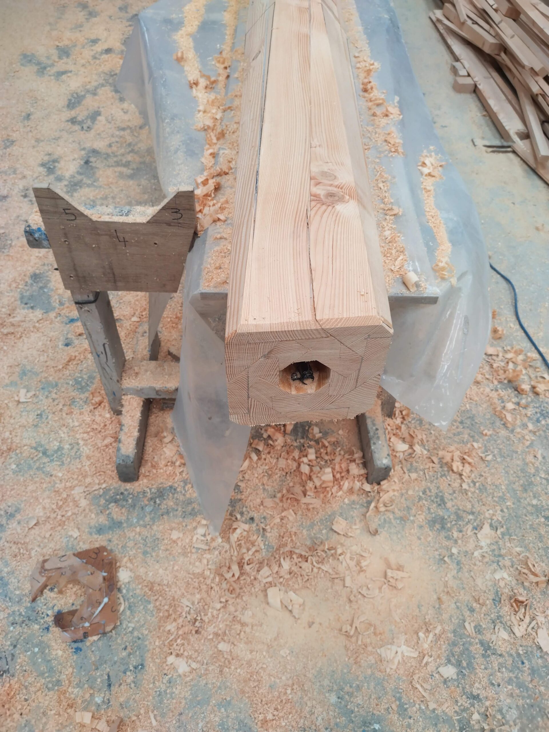
I took advantage of being in Oban to do my food shopping for the next week, and to pop into Screwfix to buy a new, better electric hand plane for the next stage. I delivered my food shopping back home and had a quick lunch, then headed back to the boatyard to inspect the mast and remove its strictures, the glue having cured sufficiently. On inspection it was evident that the birdsmouth joints weren’t as tight in some places as I’d hoped. In one place towards the head of the mast, one of the seams still had a 9mm gap between staves – a problem which I believe was probably due to some in accuracy in cutting the taper on one of the staves. In some other places there were gaps of 2-3mm for some lengths of the joints. In yet other places, the joints were tight and excess glue had squeezed out. The first job then was to somehow close these gaps. The widest gaps would have to have a spline glued in, and this covered perhaps 3m on one seam and 2m on another, both towards the masthead. For the splines I used some of the waste from cutting the tapers, which of course conveniently tapered to a point and filled the gaps nicely, with plenty of thickened epoxy to fill any remaining voids. The narrower gaps I adopted a different strategy to remedy. I masked off either side of the gap, to avoid too much overspill of tough-to-remove glue, and then mixed up a nice runny mix of slightly-thickened epoxy, which I then poured into the gaps. I used plenty, filling to overflowing, then quite often having to revisit to top up, as the runny mixture penetrated any voids. I would repeat this until the gap would take no more. I could only do a maximum of three gaps at a time, as the seams obviously had to be “downhill” so the glue would soak in and stay, not run out, so this process took several hours over a couple of days to complete. This hopefully means that at the end of it, all the seams are fully penetrated with glue and there are no voids remaining.
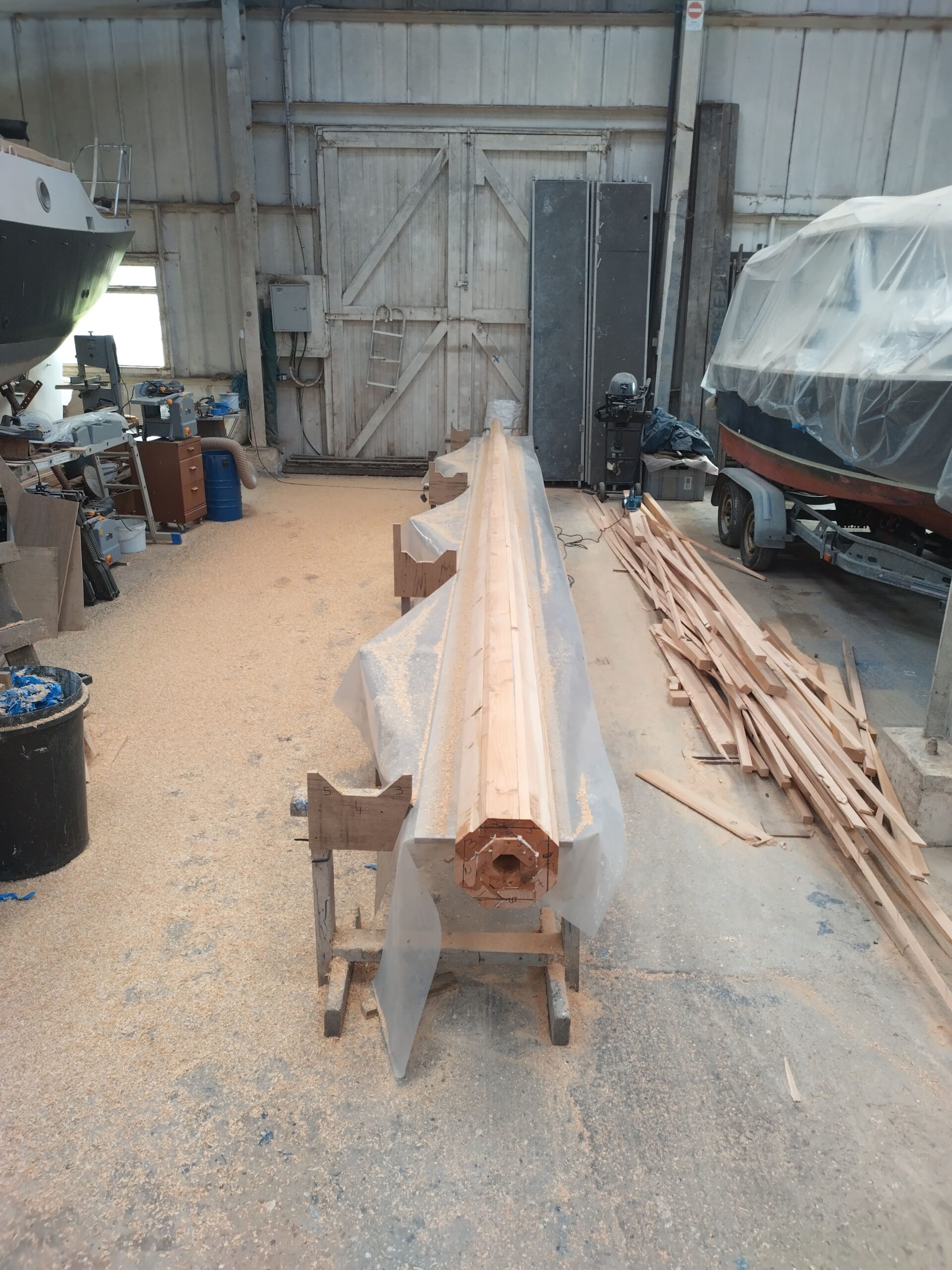
Once this epoxy had cured, I was able to plane of the “ears” to make a true octagon. The purchase of the new plane was the right decision, as I found it far easier to control than the old one, and could therefore make a more reliably neat job. This was very satisfying, and at the end of it I felt I had something approaching a mast. Unfortunately it also revealed that the assembled mast had adopted a very slight bend to it, but not that would be noticeable once it is stepped, except by me!
The next task was to plane down the bottom part of the mast (from the partners down) to a slight taper, such that the foot will fit snugly into the square mast step. For this I used the electric plane to plane alternate faces, and with the foot at the correct dimensions (as dictated by the template of the step which I had taken prior to the project start), it ends up almost square, with just a slight bevel at each corner. Once this was done I trimmed off the ends of the staves to an angle of 6 degrees to square, to allow for the forward rake of the foremast and so the foot sits flat in the step.
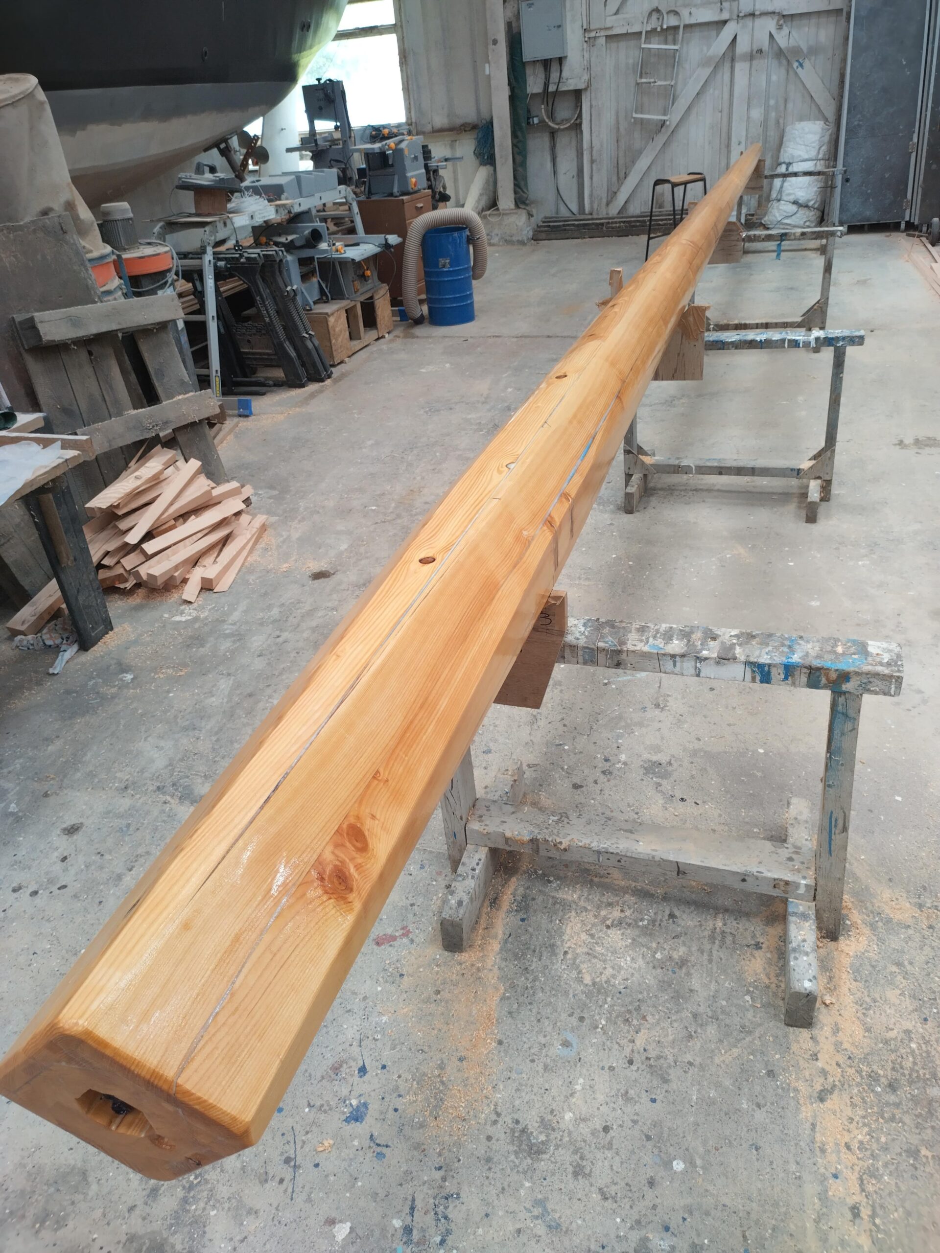
Next to start was the process of rounding the mast. I left the approx 500mm at the partners octagonal in section, meaning that fewer and less complex wedges could be used to wedge the mast in to the collar at the partners – they can be flat on the inside face rather than concave to fit a rounded section, and slightly convex on the outside face. From a small distance above the partners upwards, the mast would be rounded. The first stage of this is to plane it to 16 sides. I constructed a “spar gauge” to mark the lines of the new apexes, which wasn’t sup-accurate, but gave me enough guidance to help the human eyeball get approximately equal sides. Beyond 16-siding, it was all down to doing by eye, so I gradually worked up and down with the electric plane on a minimal setting, taking off the apexes and high spots to get something approaching a round section. Once I was satisfied with this, and importantly had got the masthead down to the right diameter to match the outside diameter of the masthead fitting (which I had taken off the mainmast, which itself will get a new masthead fitting as part of the short aluminium tube extension which I will fit to the masthead), I put down the plane and picked up the belt sander. Again I worked up and down, taking care not to dwell to long in any particular spot, taking off any remaining high spots by working radially over half the mast at a time (before turning it over and repeating), from head to partners. Finally I passed up and down with the random orbital sander, to smooth everything off. This whole process took a lot less time than I expected, and it was very satisfying to admire the rounded spar at the end of the day.
As the weekend approached, I had a couple more jobs I wanted to do before calling it a day and going back to work. First, I needed to chisel a recess at the masthead to allow the masthead fitting to slip onto the head, and to create a shoulder for it to sit on. This I did by first sawing around the circumference at the right distance from the masthead to a depth to match the inside diameter of the fitting. I then used a hand chisel and mallet to chip away the meat of the mast until the fitting slipped nicely all the way down to the newly-created shoulder. Once this was sanded, we were then ready to apply a coat of raw resin to seal the mast ready for the final stages of glassing and finishing.
At this stage it was Saturday afternoon, and after the resin was applied, I had time to head home to complete all the chores I had lined up for before I returned to work on Sunday – things like mowing the lawn, hoovering, ironing, cutting my hair and having a shower. All of these require electricity, so imagine my annoyance when I discovered we had a power cut, which had been caused by geese flying into one of the overhead cables on the island. I therefore sat staring at the wall (and reading) and cooking my supper on my single-burner gas camping stove, only for the power to come back on as soon as I sat down to eat it!
The next day I returned to work, this time in Greenock, where SD Kyle of Lochalsh was having a rather extended drydocking. Unexpectedly I got the following weekend off, so returned home and on Saturday went to the boatyard to continue my mast work. I had originally been uncertain whether I would bother with sheathing the new mast in glass or not, but given the quality of the timber, and the number of gaps I had had in the glue-up (albeit hopefully now filled), I decided it would be a worthwhile precaution to add some structural strength. As it happened, I had been given the end of a roll of 450gsm biaxial cloth by Trond, the Norwegian gentleman who had been working on redecking his boat last summer. This was just the right quantity , and a suitable cloth to add a bit of strength, as when applied in the correct orientation, the fibres run spirally round the mast at 90 degrees to each other, creating spirals of fibre in both directions around the length of the mast.
Once I had cut the cloth to suitable-sized pieces, I marked where they would lie on the mast, then on piece at a time laid them up onto the mast. This involved first rolling a coat of resin onto the mast itself, then rolling resin onto the cloth on a flat surface, so it was saturated prior to applying it to the mast. Once stuck, smoothed out by hand (with gloves of course, and very satisfying), and the edges overlapped as neatly as possible, I then rolled a resin-laden roller over the whole lot again, to ensure full adhesion and good saturation. I did most of this on the Saturday, but had to return for a couple of hours on Sunday to apply the last pieces on the sections of mast where it was lying on the horses, as it was not possible to glass bits which would then have weight on them.
What remains now is to sand the glass as smooth as possible, and then apply a couple more coats of resin, before then painting the mast with two-pack paints to a cream finish to match the coachroof sides. The painting will probably have to wait until next year, when there is space in the shed again, and I will be working on the adaptations to the mainmast. That way I can finish and paint both at the same time, and get them ready for rigging.
For now, it’s back to drydock, and another week of hard work getting KoL back in the water and ready to return to Kyle.
NB: some of the above photos are Louis’ – I have credited them where I have positively identified them as his rather than mine, but may have mis-credited one or two!